Thank you for purchasing the Turing Machine! Please follow the BOM and these instructions. Don’t populate from the PCB silkscreen or these instruction pictures alone. Our components may look different from the pictures.

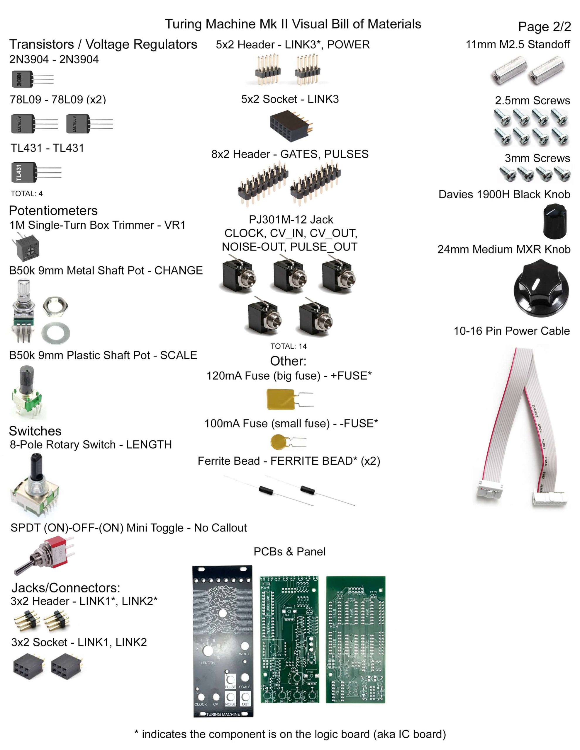
Here’s a link to a bill of materials with part numbers.
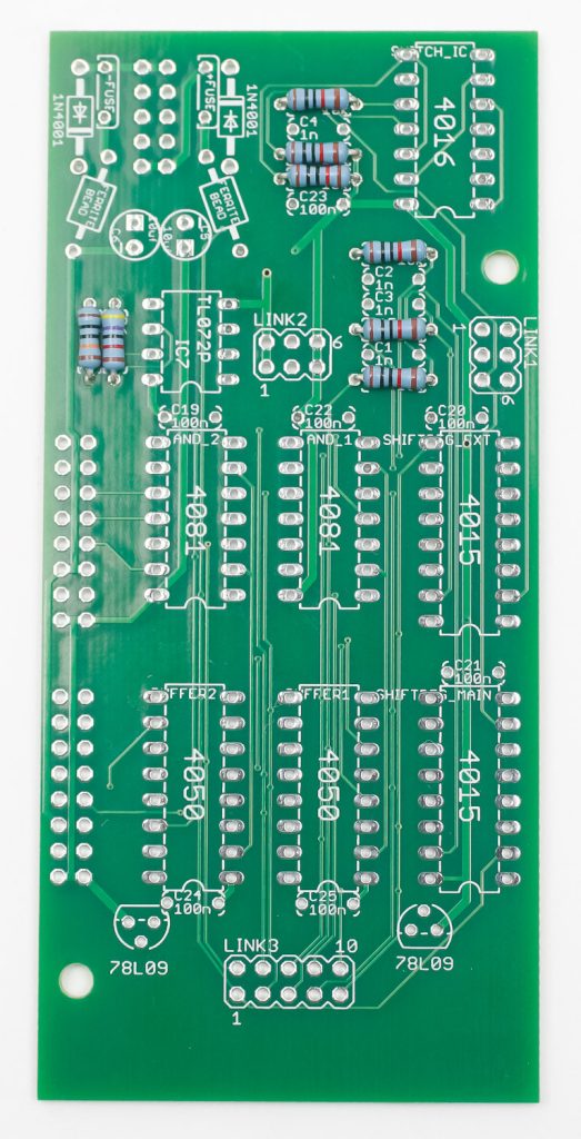
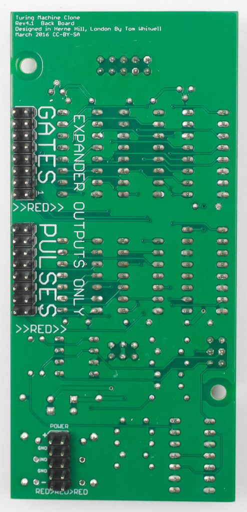
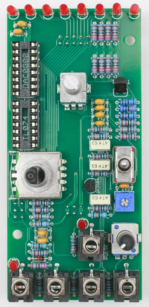
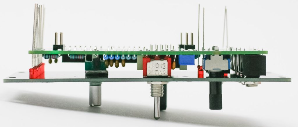
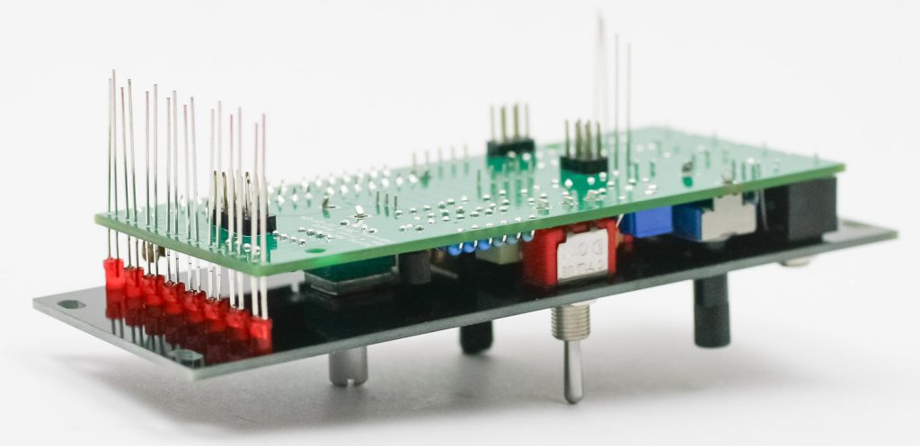
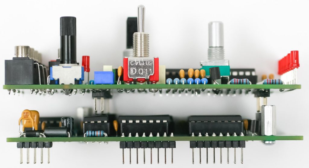
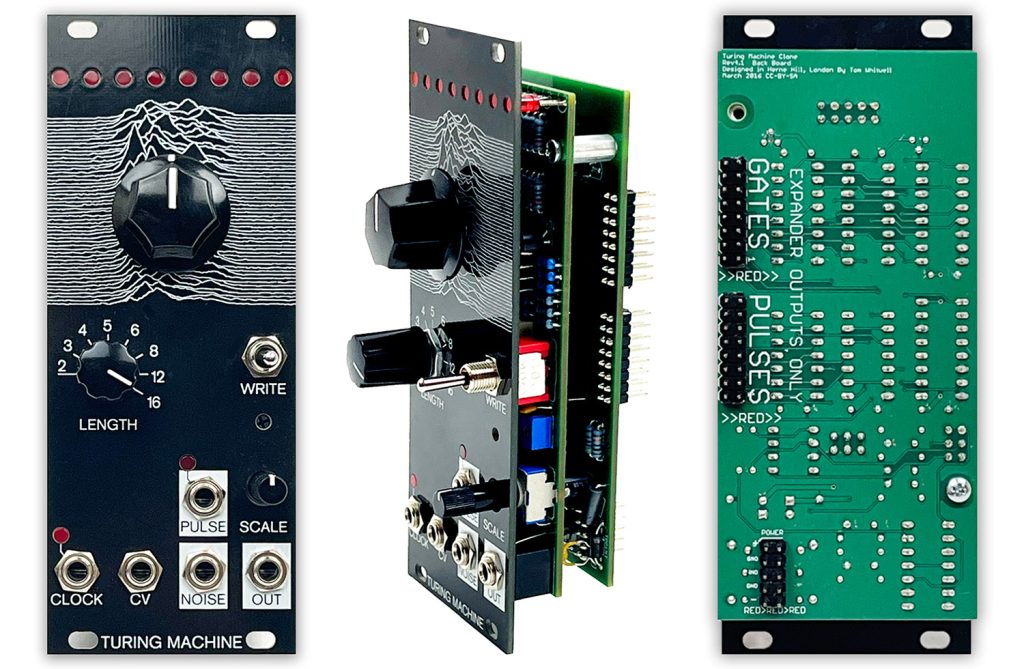
The Turing Machine has two PCBs:

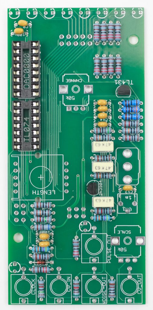
IC Board Resistors
Start with the resistors on the IC board. It helps to pre-bend the resistors before placing them into the PCB. Once have done this, carefully turn the project over (using a piece of cardboard or other PCB can help) and solder the resistors in place. Clip the excess leads.
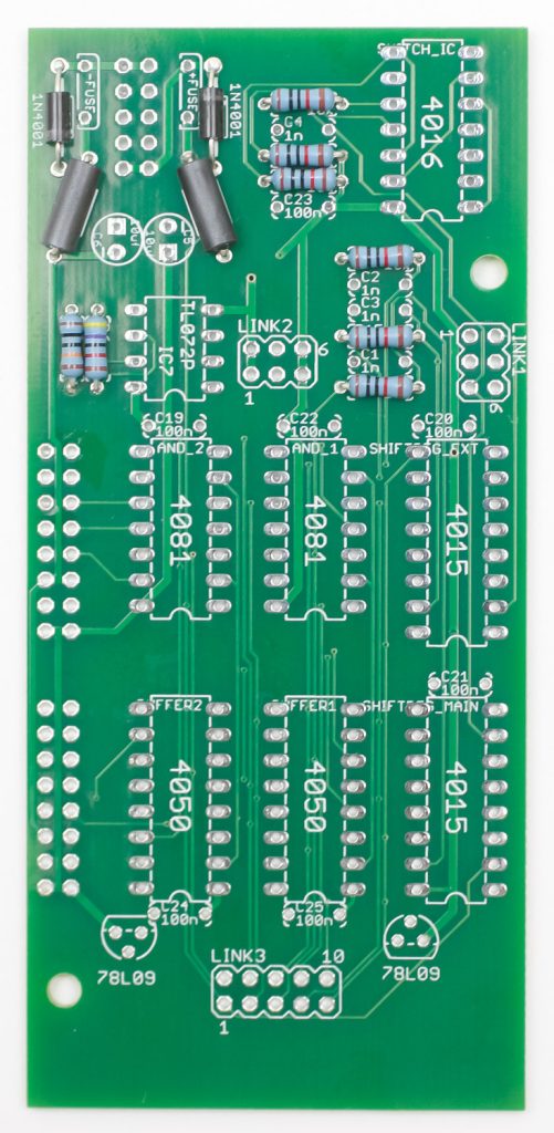
Ferrite Beads & Diodes
Diodes are polarized. Make sure you align the grey line on the diodes with the line on the PCB silkscreen. The ferrite beads can be placed either way. Again, carefully turn the project over to solder and then clip excess leads.
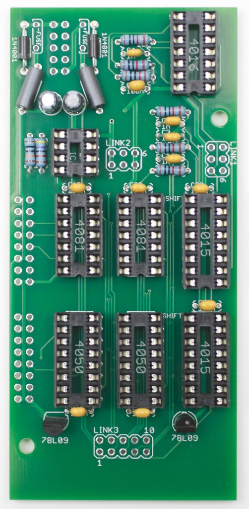
IC Sockets, Caps, and Voltage Regulators
First place the IC sockets in the PCB by aligning the notch on the PCB with notch on the PCB silkscreen. Very carefully (use cardboard or another PCB) turn the project over to solder in place. Then place the ceramic caps (non-polarized) into the PCB as shown below. Next place the two 78L09 voltage regulators into the PCB by aligning the flat edge of the regulator with the flat edge on the PCB silk screen. Turn over to solder and clip. Lastly, place the electrolytic caps in the PCB by placing the shorter of the two leads into the circular pad that has a “-” next to it. Turn over to solder and clip.
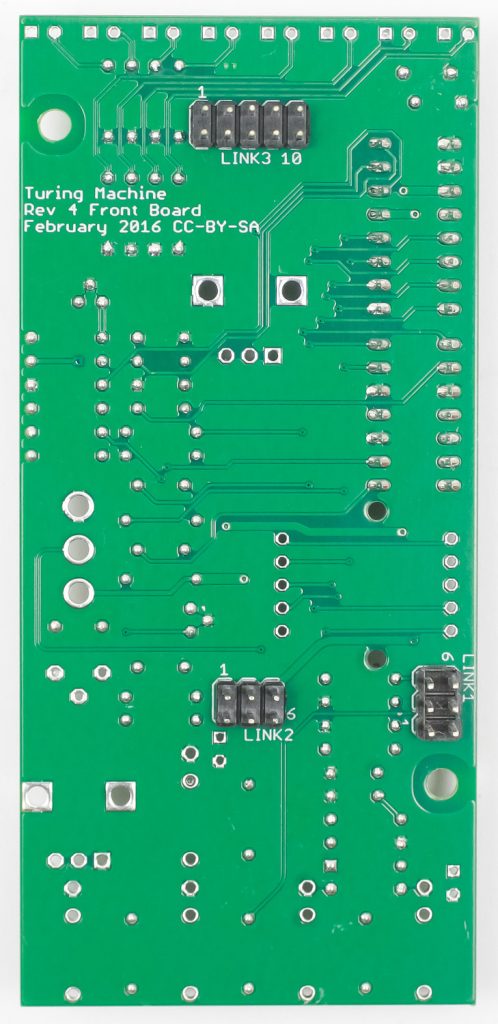
IC Board Sockets & Headers
Place the sockets into the PCB as shown below by aligning the notch on the socket with the notch on the PCB silkscreen and turn over to solder in place.
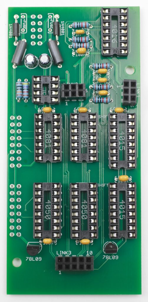
Turn the project over and place the headers in. Carefully turn over to solder in place.
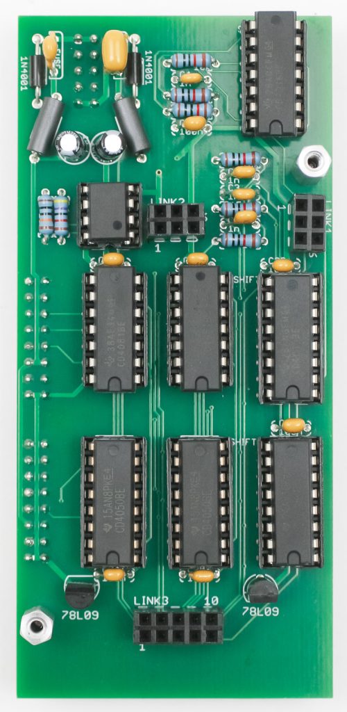
ICs and Standoffs
Populate the ICs as shown below by aligning the notch on the ICs with the notch on the IC sockets. Next, screw in the two standoffs with the provided screws.
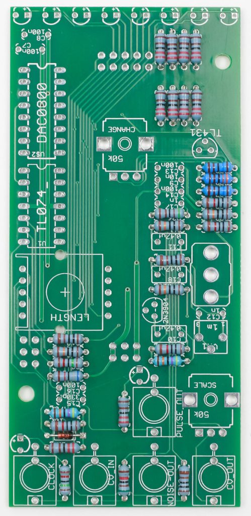
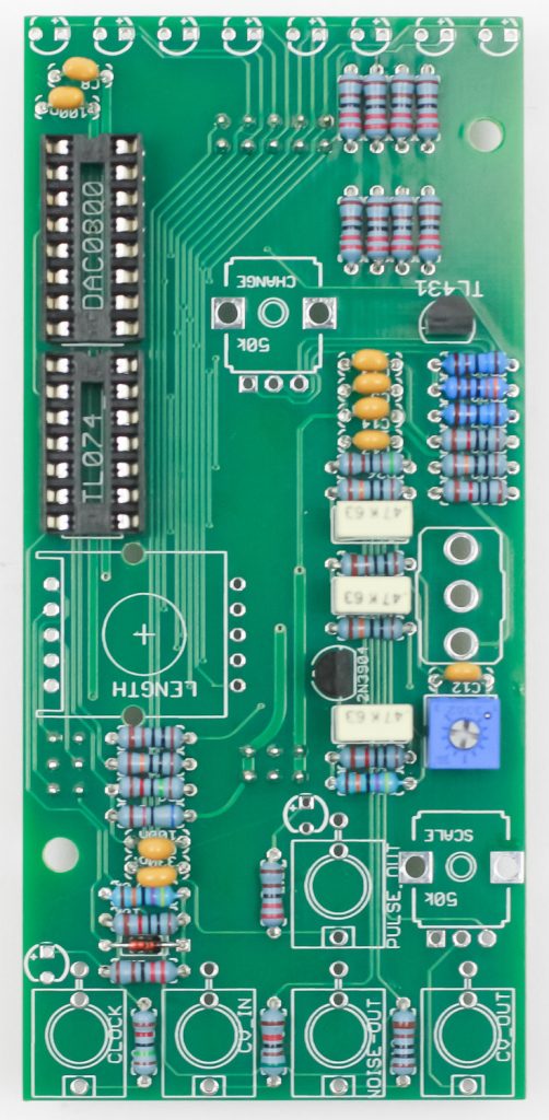
Control Board Resistors & Diode
Populate the resistors then turn over to solder in place then clip excess leads. You can now populate the diode by aligning the strip on the diode with the stripe on the PCB silkscreen. Solder and clip.
Sockets, Caps, and Transistors
Place the sockets into the PCB as shown below by aligning the notch on the socket with the notch on the PCB silkscreen and turn over to solder in place. Then place the ceramic caps (non-polarized) into the PCB as shown below. Next place the two transistors into the PCB by aligning the flat edge of the regulator with the flat edge on the PCB silk screen. Turn over to solder and clip.
Control Board Headers
Place the headers into the PCB, carefully turn over to solder in place.
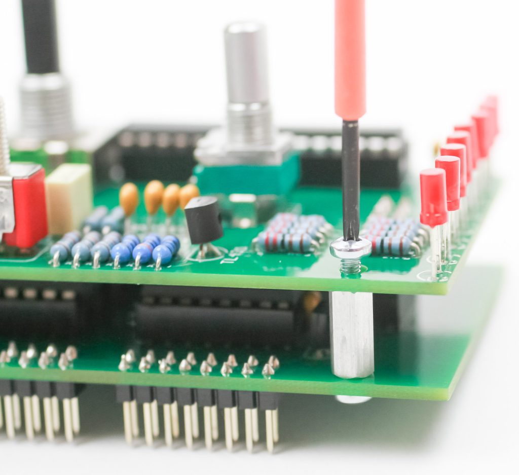
Trimmer Resistor
Place the trimmer resistor in the PCB, turn over and solder in place.
Panel Prep, LEDs & other Parts
Take some masking tape and cover up the LED holes as shown below
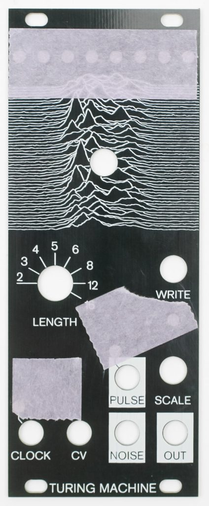
DON’T SOLDER YET! Now place the LEDs into the PCB, placing the longer lead into the pad that has the “+” next to it. Loosely do this as well for the switches, jacks and pots.
Now take the panel (with tape over the holes) carefully place it over the control board. Finger-tighten the nuts then turn the project over.
Let the LEDs hit the tape as shown below. You can now solder in place the LEDs, jacks, switches and potentiometers. Clip excess LED leads.
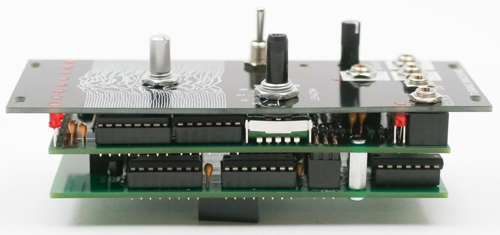
Board to Board Connection
Remove the panel and now connect the two boards together carefully. Align the sockets and headers.
Once connected, screw down the Control Board to the IC board with the provided screws.
Final Assembly
Finally place the panel over the project again then gently tighten down the jack, pot and switch nuts. You can now put the knobs on.
Congrats on your build! You are now ready for calibration and testing.
Calibration
Setup:
- Set LENGTH switch to “8.”
- Set big knob and SCALE knob to max, fully clockwise.
- Patch a square wave from an oscillator into the CLOCK input.
- Patch the OUT to the audio output of your Eurorack system.
Using a small Philips screwdriver, start by turning the trimmer (located just below the WRITE switch) fully clockwise.
Turn the trimmer counter-clockwise until you hear a stable, consistent tone; then turn the trimmer clockwise again until you hear the tone “break up” or “glitch.” Turn it counter-clockwise again in tiny increments until the glitching goes away. After each small adjustment, wait 10 seconds to make sure it doesn’t glitch again.
Once the trimmer is set, turn the big knob fully counter-clockwise; it should have a steady tone as well.
The module is now calibrated and ready to use!