Important Links
Product Page
Store Page
Assembly Instructions
Bill of Materials
QC Instructions
Teensy Setup
SD Card Setup
Manual
Github
AirWAV Assembly Instructions
Thank you for purchasing the Sound Study Modular AirWAV kit!
ATTN: Please follow the BOM and these instructions. Don’t populate from the PCB silkscreen or these instruction pictures alone. Our components may look different from the pictures, so please look over your parts and check the codes first.
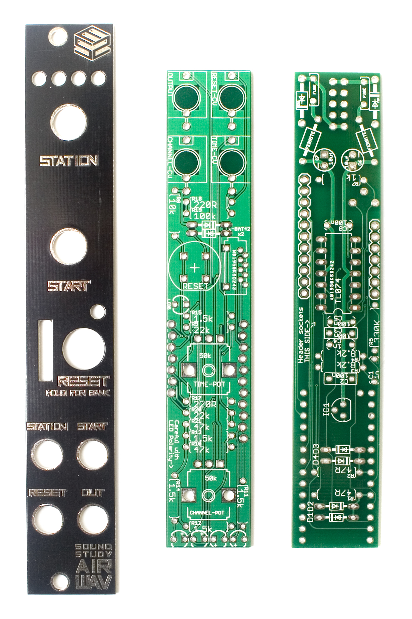
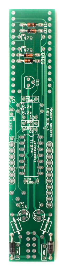
Logic Board
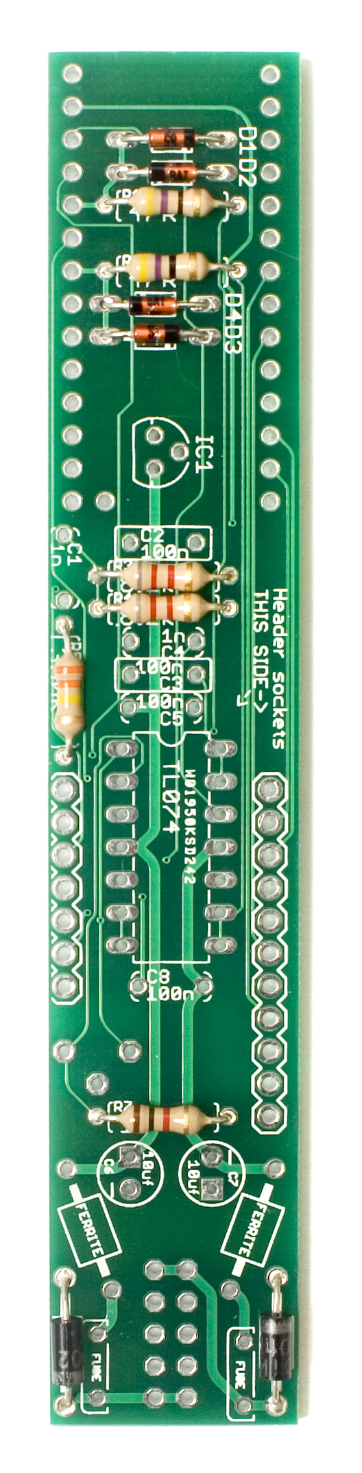
Diodes
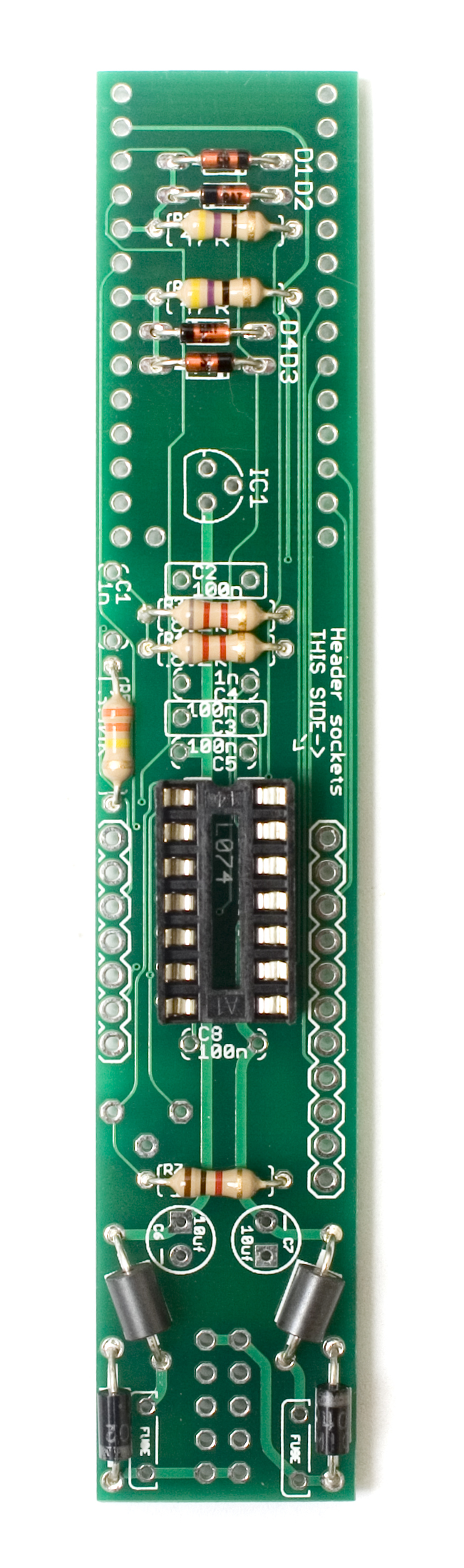
First up are the diodes, there are 4 smaller orange ones, and two larger black ones. Following the BOM, make sure you get these in the right spots, and with the proper orientation. Diodes are polarized, so make sure to line up the cathode marking (stripe) on the diode itself with the cathode marking (stripe) on the PCB. Once you have these guys in there, go ahead and carefully flip your project over, solder them in place and clip any excess leads.
Resistors
Now we can populate the resistors. These are non polarized so it does not matter which way you insert them into the PCB. If you align them all so that the tolerance bands (usually a gold stripe) all face the same side, then any troubleshooting you may need to do later would be much easier. Once you have them populated in the proper spots as per the BOM, carefully flip your project over and solder them into place, clipping any excess leads.
Ferrite Beads
Next up are the ferrite beads. These are non polarized, so it doesn’t matter which way you insert them into the PCB. Once you have them populated, carefully flip over your project, and solder them in place, clipping excess leads.
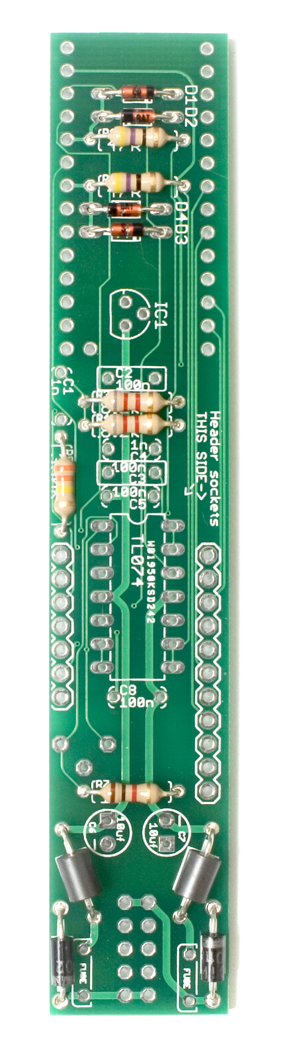
IC Socket
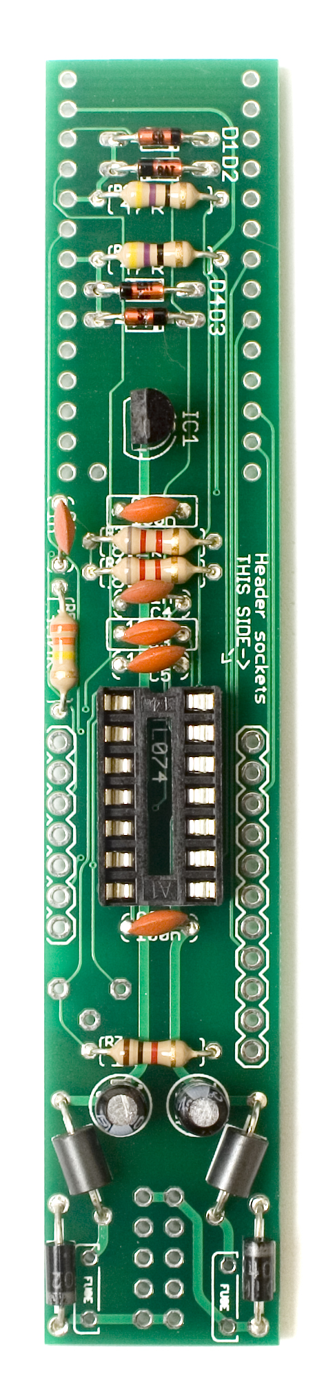
Next up is the IC socket. These sockets have a semicircular notch in one side to indicate where pin one is. Ensure that you align this notch with the same notch on the PCB. This will help ensure that you insert the IC correctly. Once its in there properly, flip the project over and solder in place. A trick to get these to sit flat is to only solder one leg to start, and then while applying gentle pressure, re heat the pin that you soldered and pushing it flat against the board.
 Capacitors and Transistors
Next we can do all of the capacitors and transistors. If you sourced your own parts, you may have to do the electrolytic one second, if they are larger than the rest of the components.
The ceramic capacitors (little orange disc looking ones) are non-polar, so you can populate them any direction you would like, but we recommend installing them in a way that makes them easy to read once everything else is installed.
When populating the transistor, make sure that you align the flat side of it with the same flat indicator on the PCB. You may need to spread the leads apart a little bit in order for it to fit.
The electrolytic capacitors are polarized, so take care when populating them to make the stripe (cathode) line up with the minus sign on the PCB.
Once everything is in, flip your project over, solder everything in place, and clip any excess leads. You may want to use the help of a piece of plastic or cardboard to help you flip the project over so that nothing falls out while doing so.
Sockets
Now we can populate the board to board sockets. Grab your 11 pin and 7 pin sockets, and insert them into the side of the PCB with the silkscreen for them. (opposite the side of the teensy) Solder one pin to start, and then while reheating the pin, gently apply pressure to flatten and re-align the sockets so they are flat to the board, and straight. Then you can go back and solder the remaining pins.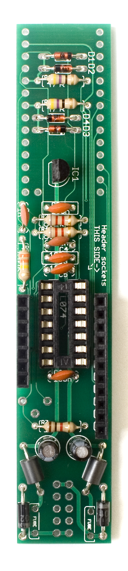
Fuses
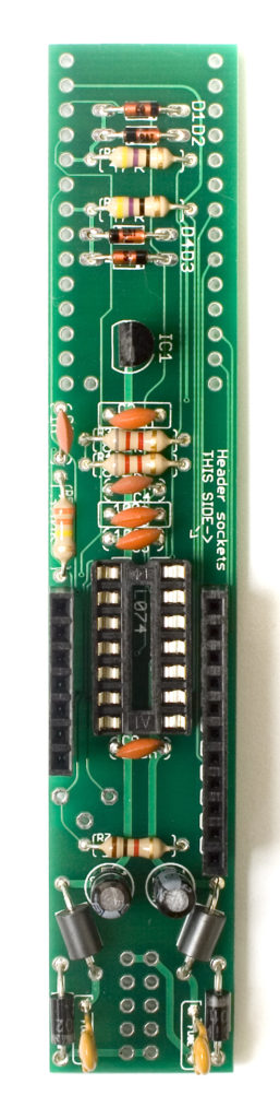
Next up are the resettable fuses. These guys are going to stick up pretty far, but insert them into the PCB as far as they can go, without pushing too hard. They aren’t polarized, so it does not matter which direction you orient them in. Once populated, carefully flip the project over and solder them in place, clipping excess leads.
 Trimmer Potentiometer

On the bottom of the logic board, there is a spot for the square trimmer potentiometer. It should only fit one way into the PCB, with the legs sliding easily into the PCB and the box part lining up with the silkscreen. Once in, flip your project over and solder in place. (be careful not to melt the socket when soldering this in place!)
 Power Header
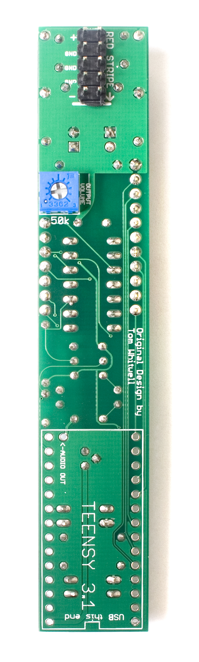
Next up is the 5×2 unshrouded header for the power cable. Populate it in the proper spot, and then solder in place. When soldering, you may need to bend the fuses out of the way in order to get your soldering iron into position. Be careful not to melt anything while trying to solder this header in place. Use the same trick as before on the 7 and 11 pin sockets to get this header soldered flat and straight as well.
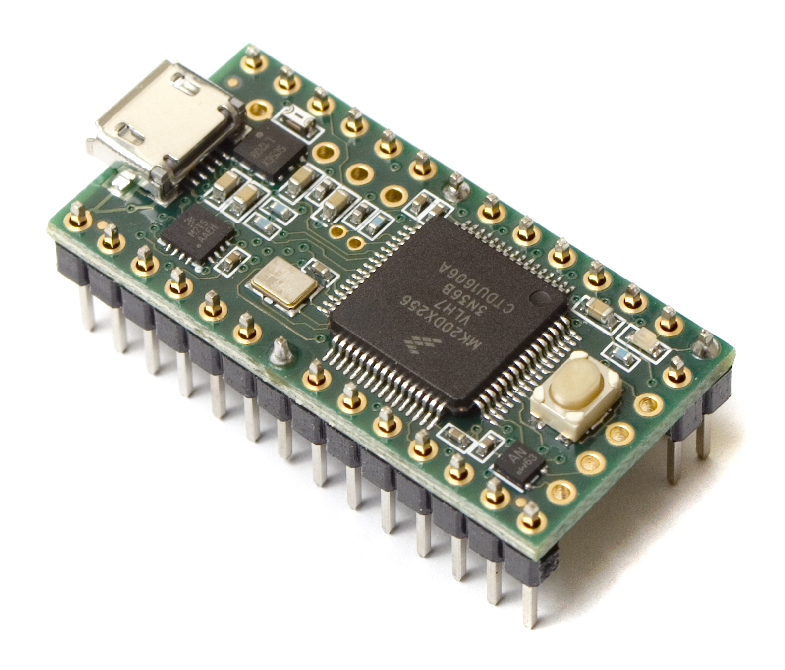
Teensy Prep
Your Teensy may or may not have come with headers soldered to it already, or if you had one left over from another project, it may have a different pin configuration. As long as it has the same pins soldered in as the way we are about to describe, extra pins do not matter, and won’t interfere with the installation process.
For the next couple steps, we are going to use the following headers and sockets:
- 14 Pin Header & Socket
- 13 Pin Header & Socket
- 2 Pin Header & Socket
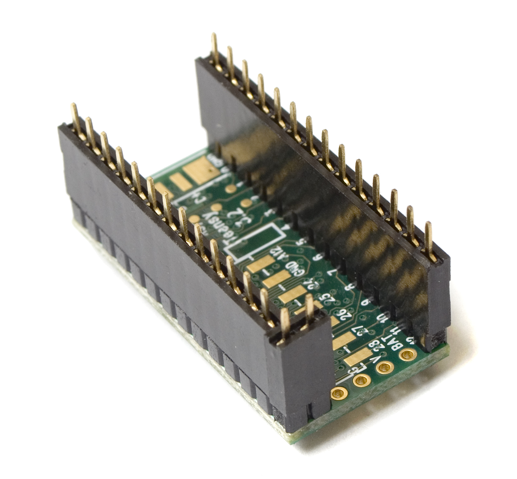
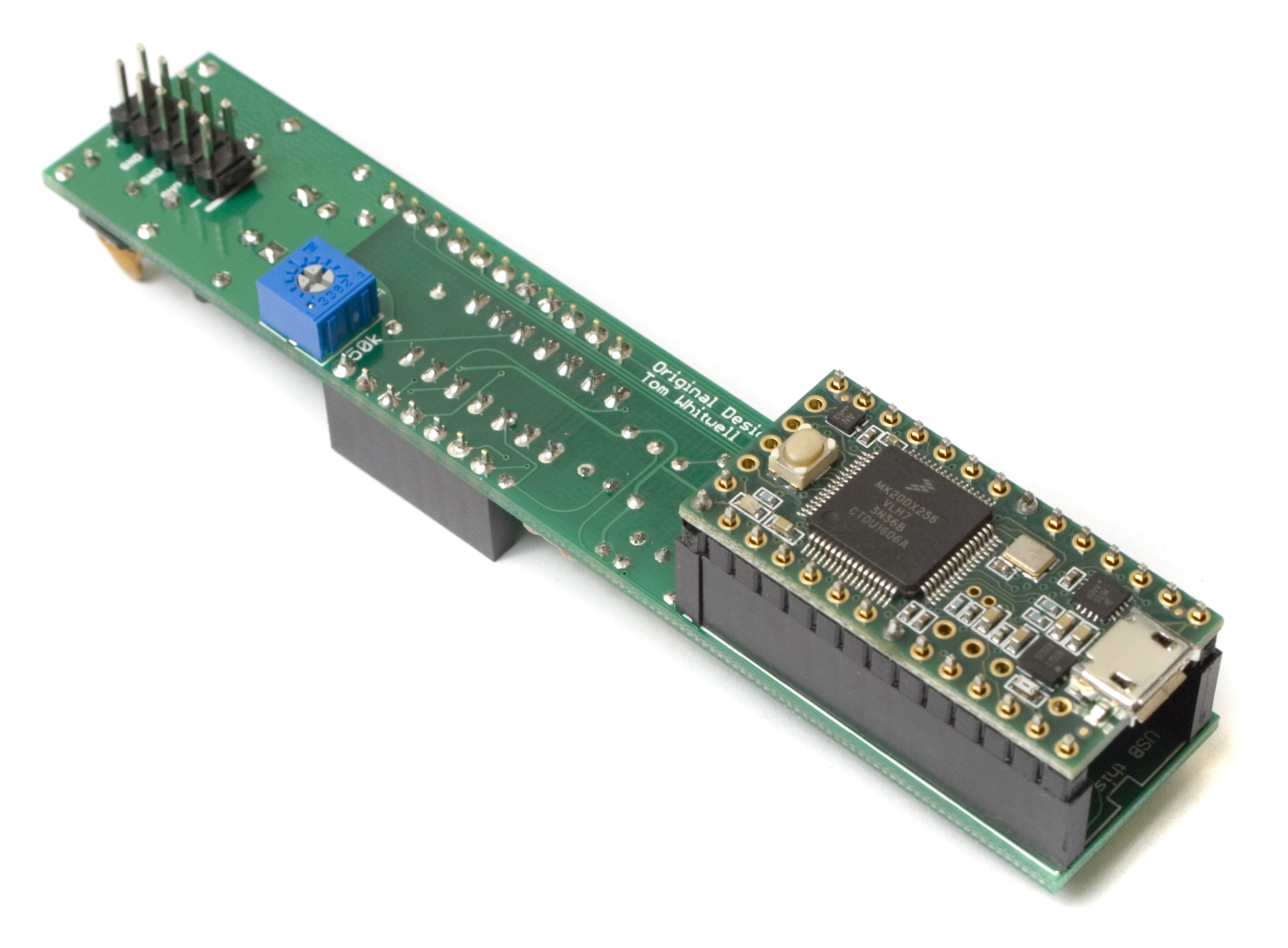
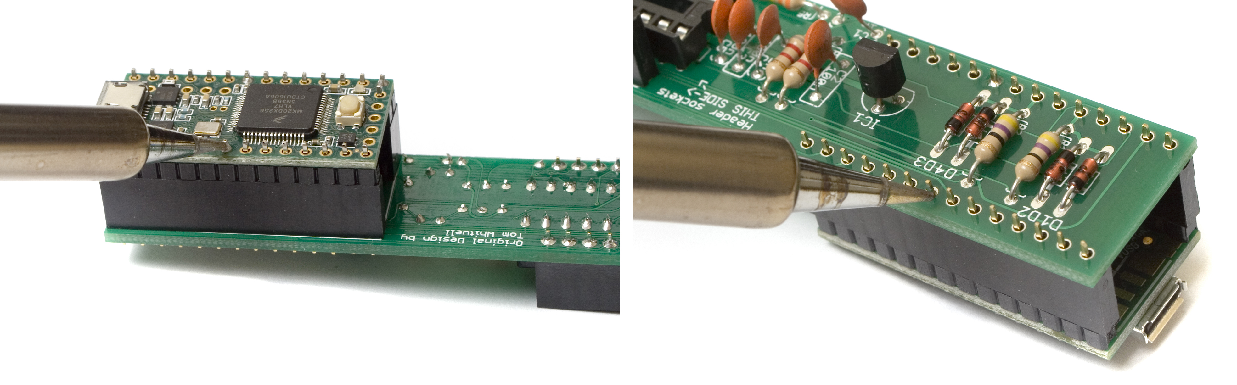
Grab the 3 headers, and populate them so that your Teensy looks like the one below.
Flip it over, and solder only one leg of each for now, just to hold the headers in place.
Be VERY careful soldering on the Teensy! Don’t touch anything but the pins with your soldering Iron, and make sure not to bridge any components on the Teensy to the pins when soldering!
Next, flip the teensy over, and place the three female sockets onto their male header counterparts.
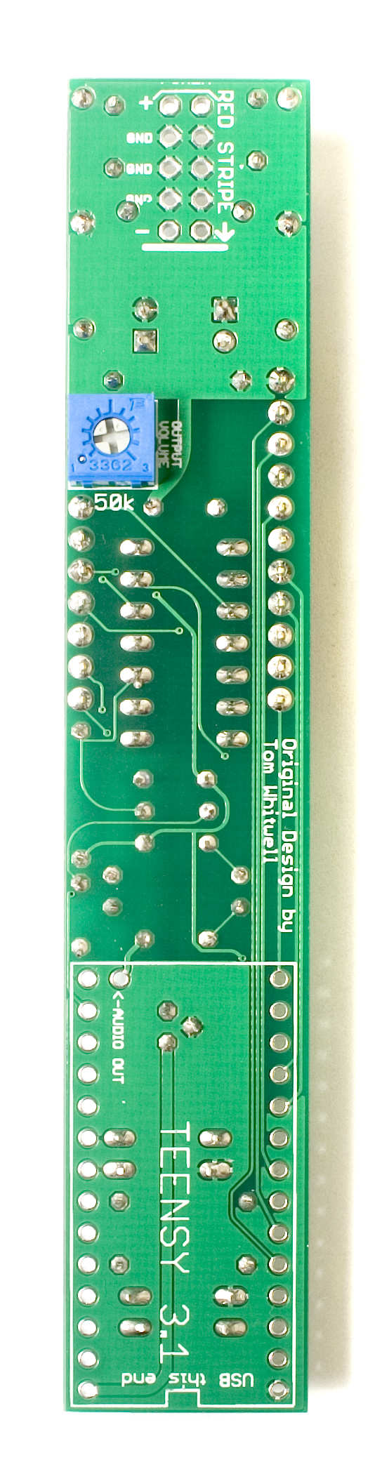
 Now insert the whole assembly into the bottom of the logic board, making sure to align the USB jack on the Teensy with the short edge of the board. Solder only a couple pins on the top of the logic board, to hold the assembly in place temporarily.
 Once everything is together, you can re-heat the three headers on the Teensy and the logic board, making sure that the header/socket combos are straight and even.
Be VERY careful soldering on the Teensy! Don’t touch anything but the pins with your soldering Iron, and make sure not to bridge any components on the Teensy to the pins when soldering!
 Once you are satisfied with the placement of the Teensy assembly on the logic board, solder all the remaining pins on the headers and sockets, making sure everything stays flat and even.
Control Board
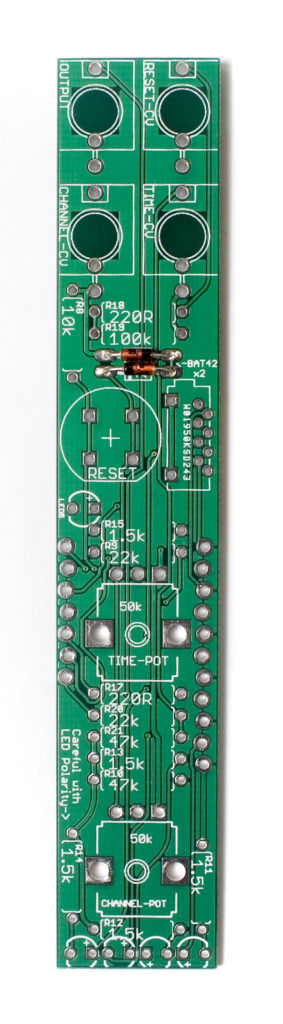
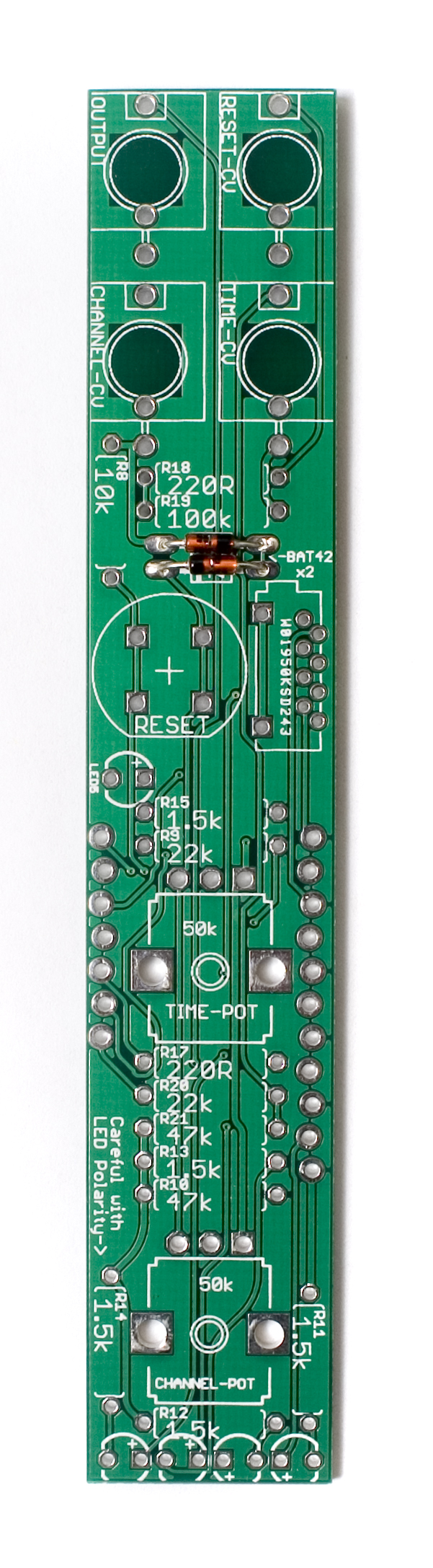
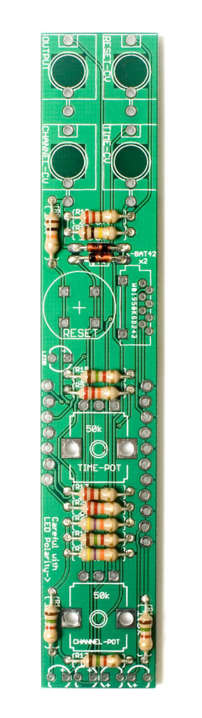
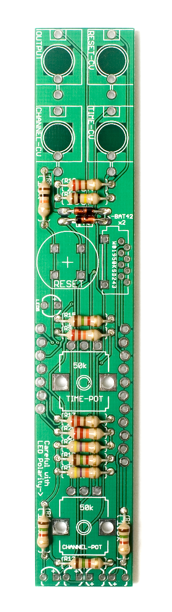
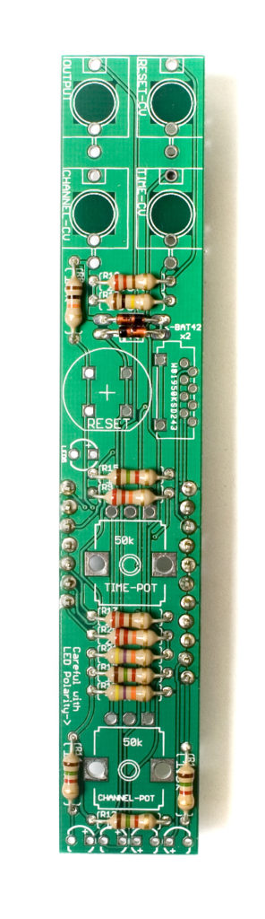
Next up is the control board. Start with the diodes, making sure to line up the black cathode band with the stripe indicator on the PCB.
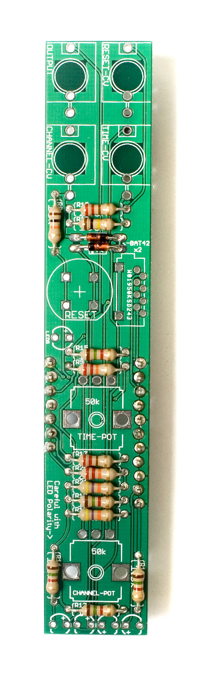
 Resistors
Next up are the resistors. Populate them as before, and then carefully flip over and solder them in place, clipping the excess leads.
 Header Prep
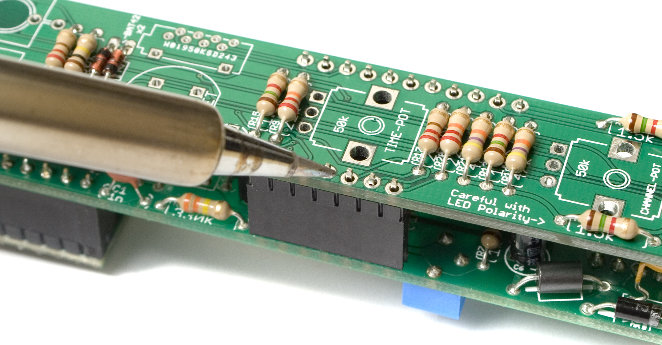
Next up, we are going to solder in the board to board headers. Start by inserting the 7 and 11 pin male headers into their counter parts on the logic board, as shown below.
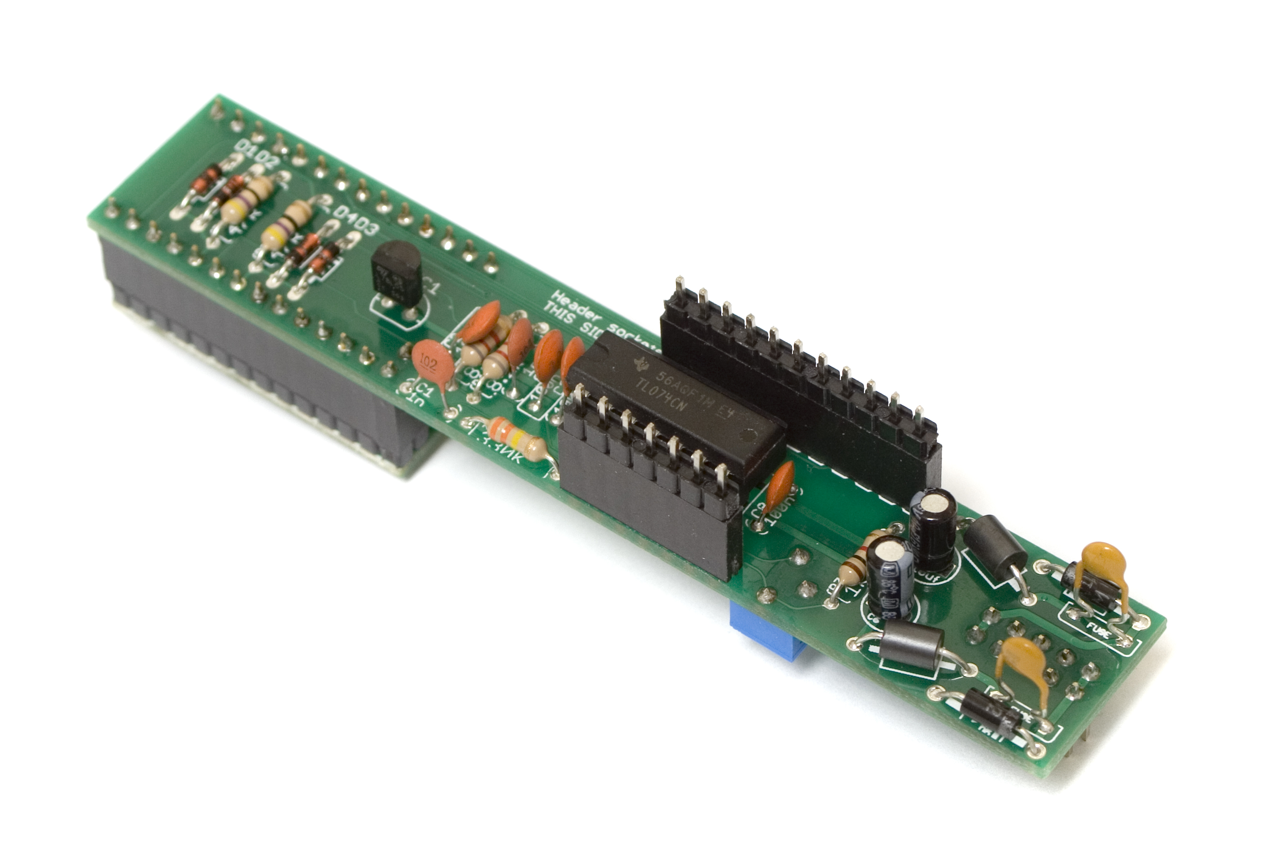 Next, place the control board onto the headers so that the header pins are sticking though the PCB. Make sure that the PCB is nice and flat, as well as parallel with the logic board, and then solder it in place.
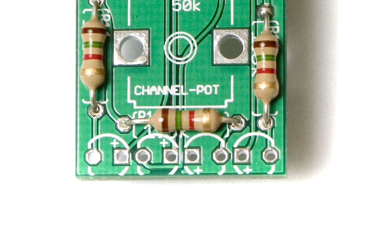
 The control board should now look like this:
 Hardware and Front Panel
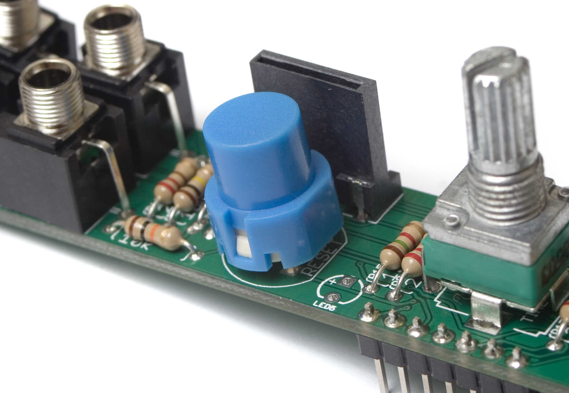
Now we are ready to populate all the hardware and get the front panel mounted. Be careful with the LED polarity, as they are not all facing the same direction. See the picture below for clarification:
 Alright, populate all the components as per the BOM. Make sure there aren’t any nubs alignment keys on the pots, and if there are, remove them with a set of pliers or side snips.
When placing the SPST button, make sure to align the flat side of the switch with the same flat side indicated on the PCB’s silkscreen.
Once you have everything populated, place the front panel down over all the components.
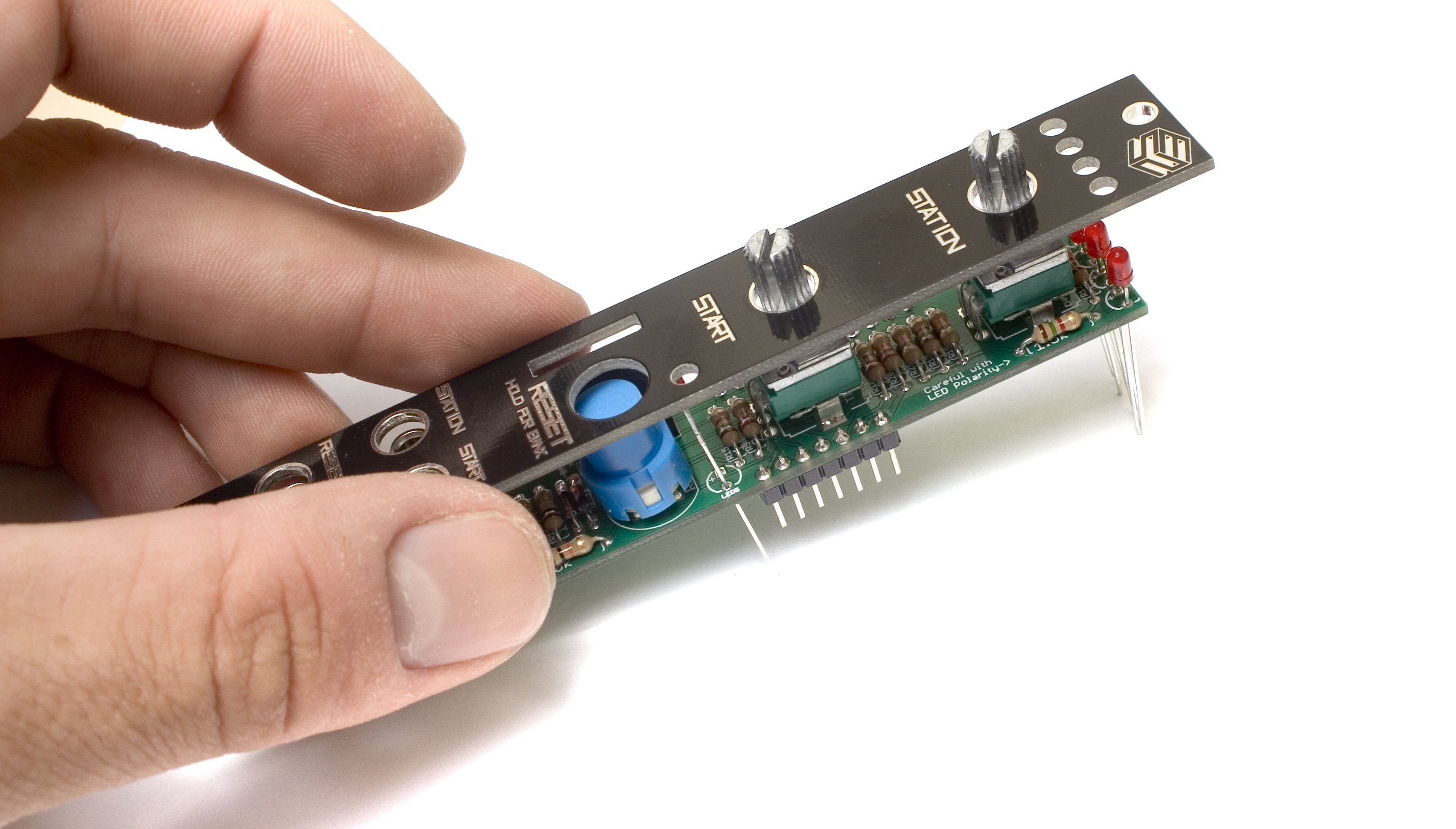 Use a tool to tighten the nuts on the potentiometers and jacks, but be careful not to over tighten the nuts.
 Soldering It All in Place
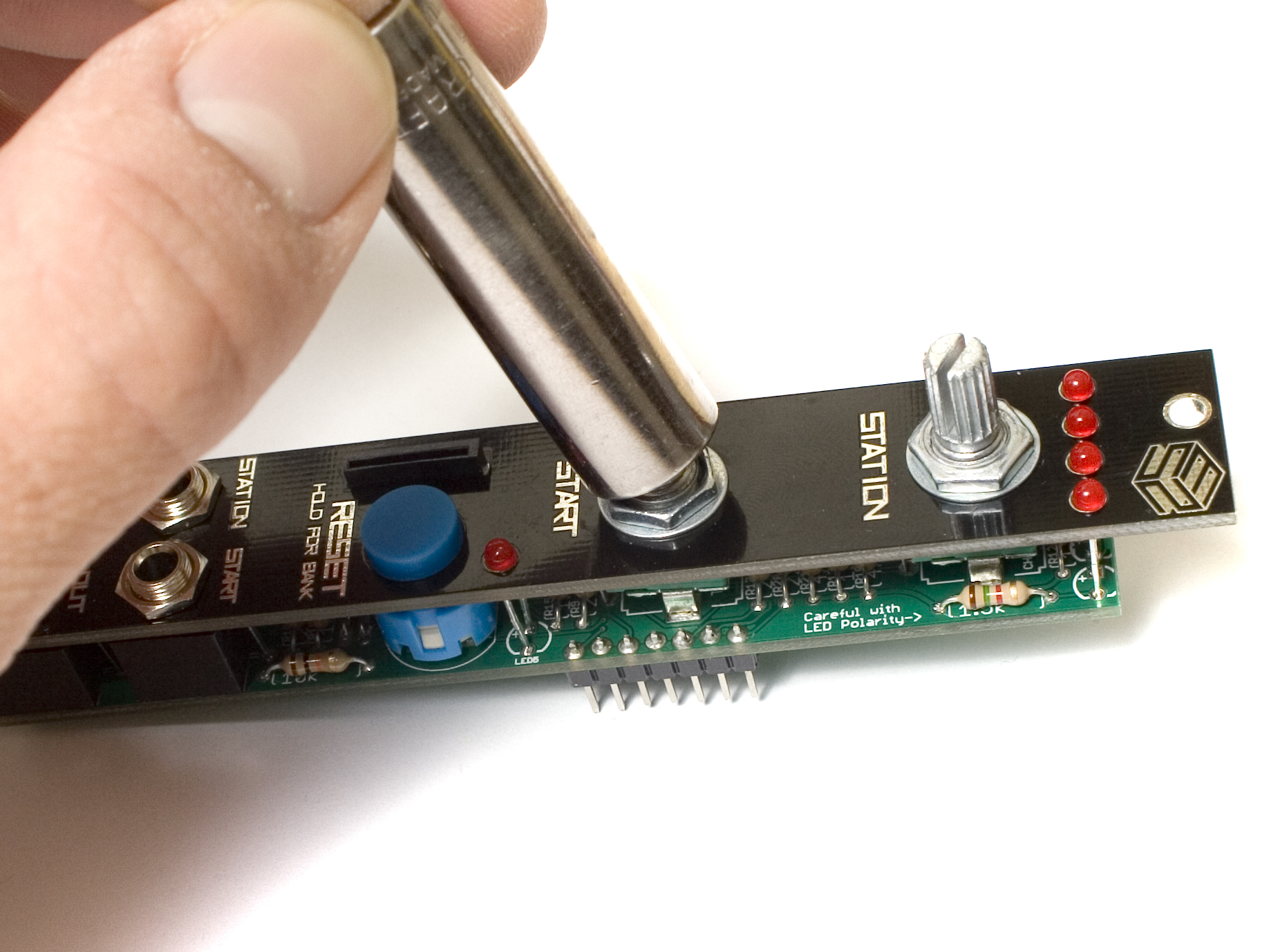
Next, carefully flip your project over and solder the components in place. Make sure everything is nice and straight, and flat before soldering. You may want to consider soldering only one leg of the LEDs first, then making sure they are fully seated in their holes, then soldering the other leg. Clip any excess leads.
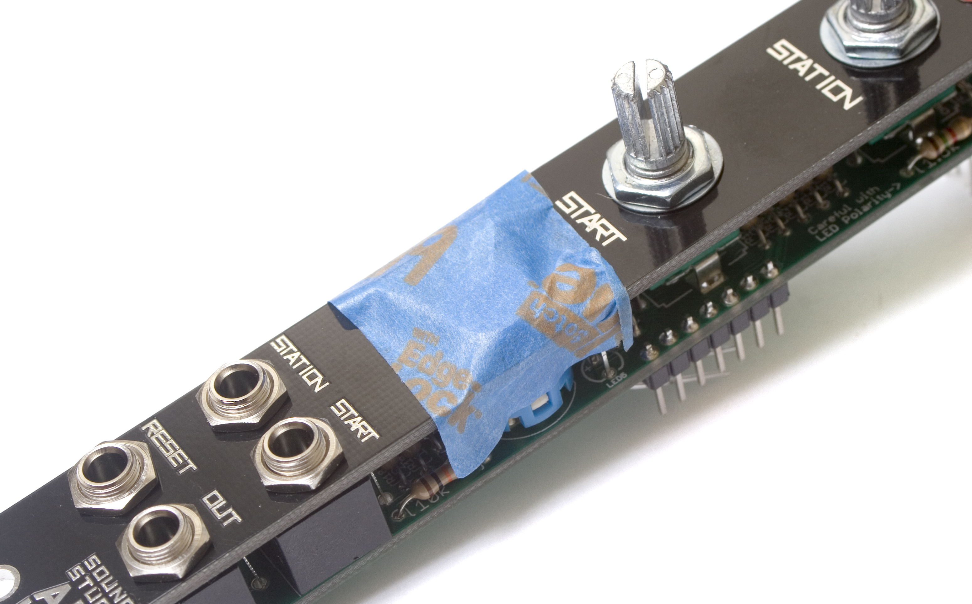
To get the button and SD card soldered in, it is recommended to use a piece of tape to hold them down while soldering. Place the tape as shown below, then solder only one pin of each. Then take the tape off and reheat while applying gently pressure to re-align them to the board. You want to make sure they are straight, and the front panel doesn’t interfere with the button’s action. Once you are satisfied with the results, solder them in place.
Completed Module
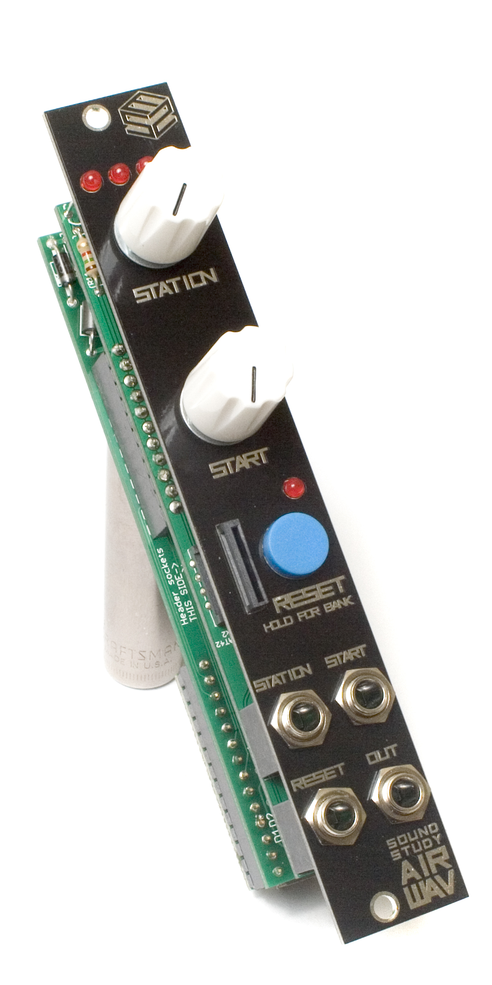
Congratulations! You’ve just completed the Sound Study Modular Air WAV! You’re almost ready to give this module a test run, but before you do, the Teensy needs to be set up properly, and the SD card needs to be filled with samples. Please see our Programming section to set up the Teensy, and our SD Card Prep section to set up the SD card.
Have any issues with the build? See our Troubleshooting guide for some basic tips and tricks, or shoot us an email at soundstudymodular@gmail.com
QC Instructions
Now that you have the Sound Study Modular Air Wav built, it’s time to see if it is working properly. To do this, you will need:
- Completed Air Wav Module
- SD card prepped with audio files. (how to do it)
- Patch cables
- other modules to generate CV and triggers
- Small screwdriver for the trimmer
First, plug in the Air Wav to power, making sure to orient the power cable such that the stripe on the cable matches the stripe indicator on the back of the module.
Turn on you modular system, and run a patch cable from the output of the Air Wav to your output module. (or plug headphones directly into the Air Wav.)
It should already be playing the first audio file on bank 0. If not, double check that your sd card is formatted properly, and that the firmware was uploaded to the teensy without issue.
Adjust the trimmer on the back of the module so that the audio coming out is as loud as it can be, WITHOUT distortion.
Next, sweep the station knob back and forth slowly, and make sure that the Air Wav is changing audio files when you move the potentiometer.
Move the Start knob so that it is pointing straight up, and then tap the reset button. This should restart the current audio file at about halfway. The start knob will not have any perceivable function until either the reset button is pressed, or the reset jack gets a trigger.
Reset both knobs to full CCW position.
Patch a CV source into the station jack, and feed various CV amounts into the jack, making sure that the audio files change with the different CV amounts. If you hear ‘jittering’ or ‘static’ it is normal, you are just on the border between two audio files. Try adjusting the station knob just a little until it is clear. This will become hard to do the more files you have per bank.
Take the CV source out of the station jack, and patch it into the start jack. Now when you press the reset button, the audio file should start at different points in the file. 0v would be at the beginning, and 5v is near the end. The CV is additive to the knob, so if you have the knob pointing up, and give it 1v on the start jack, the audio file will start about 3/4 the way through.
Next patch a trigger or clock into the reset jack. Every time the signal goes high, your audio file should restart playing either from the beginning, or wherever you have it set as per the jack/knob.
Now HOLD the reset button down, and you should see the LEDs up top changing, indicating which bank you are on. There is a table in the manual that shows how to read the LEDs and determine what bank you are in.
That’s it. If everything checked out okay, you are good to go!
If you have any questions about weird functions or possible errors, feel free to shoot us an email at soundstudymodular@gmail.com
Preparing the Teensy
In order to get the Teensy ready, you are going to need the Teensy Loader. It’s available for Linux, Windows, and Mac. You only need the Teensy loader, and not the Teensyduino or Arduino software unless you are going to write your own firmware. You will also need a micro USB cable (like the ones for android phones) Make sure its a data cable, and not a charge only cable.
Once you have the Teensy Loader installed, make sure it is working by flashing the fast/slow blink programs.
If you are having issues getting the Teensy to work with the loader, check out the Teensy troubleshooting page.
When you have everything set up, grab the firmware here, and then in the Teensy Loader, go to File -> Open, and open the file you just downloaded. It should end with “.hex”. Make sure you unzip it, if it is zipped.
Press the button on your Teensy, and the software will load the hex file onto your teensy. Done!
Don’t ever plug in both modular power and a usb cable from your computer at the same time! This will damage the Teensy!
If you plan on doing firmware updates while its plugged in, or need to have both modular power and usb hooked up, make sure you cut the power trace for the usb on the bottom side of the Teensy. The one you want to cut is a very small trace between the two smaller rectangle pads shown below in the red circle.
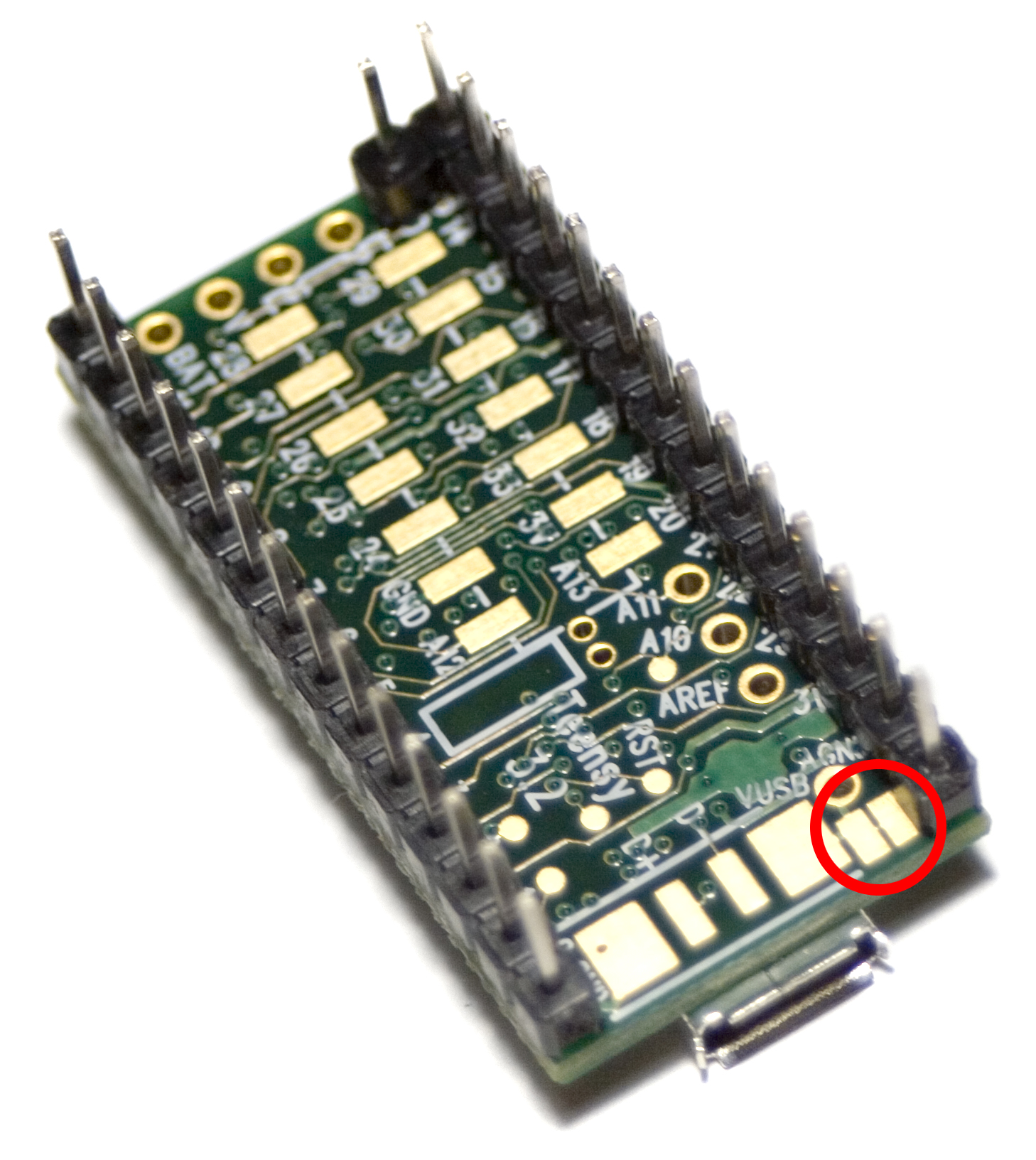
Cut the USB Power trace between the two pads circled in RED, above.
TOP
Setting up the SD Card
When selecting your SD card, make sure you get a decent brand, as these have the highest transfer speeds and tend to last longer than the cheaper brands. The maximum size that the Air Wav will recognize is 32Gb.
Make sure that it is formated in either Fat16 or Fat32 format. It most likely is already formatted properly, but its good to double check.
The files that you upload to the card need to be:
- Mono
- 16 Bit
- 44.1 kHz
- Headerless Wav files using the .raw suffix
The Module will recognize up to 16 folders in the root directory of the SD card, any more may cause it to crash. It will ignore any subdirectories inside of these folders.
Each of the 16 folders is a different ‘bank’ on the module.
The max number of files per bank is 75. The module itself has an overall limit of 300 files. Keep in mind that all the files per bank are going to be selected with one potentiometer, so limiting the number of files per bank is crucial if you want to be able to easily select them individually.
The filenames must be in 8.3 format. Which means at most 8 characters, then a period, then at most 3 more characters for the file extension. Any more, and the module may not work properly, or at all. An example would be “NOISE.RAW”, or “DRUMLOOP.RAW”.
Below is an example file format:
- Root Directory
- 0
- FILEONE.RAW
- FILETWO.RAW
- FILETHRE.RAW
- 1
- RANDNOIS.RAW
- DRUMLOOP.RAW
- 2
- ABC.RAW
- DEF.RAW
- ABCDEFGH.RAW
- 3
- FILEONE.RAW
- FILETWO.RAW
- FILETHRE.RAW
- 4
- FILEONE.RAW
- FILETWO.RAW
- FILETHRE.RAW
- 5
- 6
- 7
- 8
- 9
- 10
- 11
- 12
- 13
- 14
- 15
- 16
- 0
‘0’, ‘1’, ‘2’, etc. are all folders in the root directory, and ‘FILEONE.RAW’ are the actual files. Make sure there aren’t any other files on the SD card except the folders and the raw files. The module will create a settings.txt file on the card, which is editable.
To convert your files into headerless wav file format, you can use either Audacity, which is cross platform, or Sbooth MAX. (mac only)