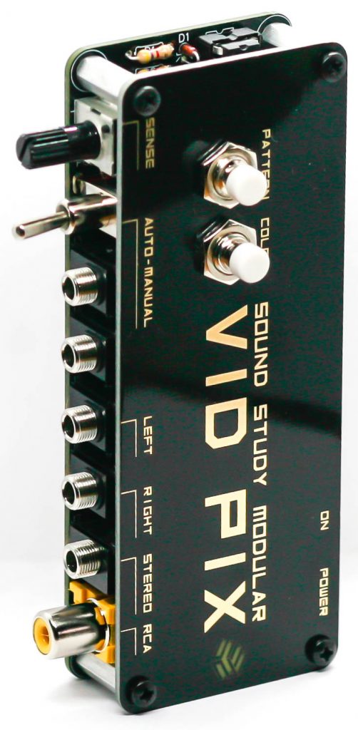
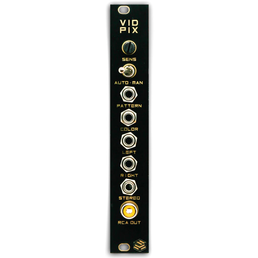
Thank you for purchasing the Sound Study Modular VID PIX! These assembly instructions are for the Eurorack and console versions.
ATTN: Please follow the BOM and these instructions. Don’t populate from the PCB silkscreen or these instruction pictures alone. Our components may look different from the pictures, so please look over your parts and check the codes first.
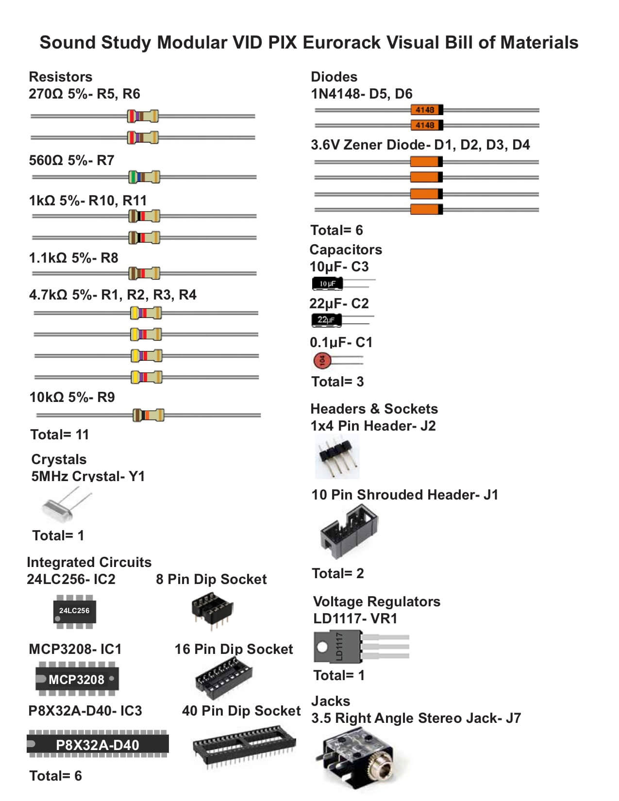
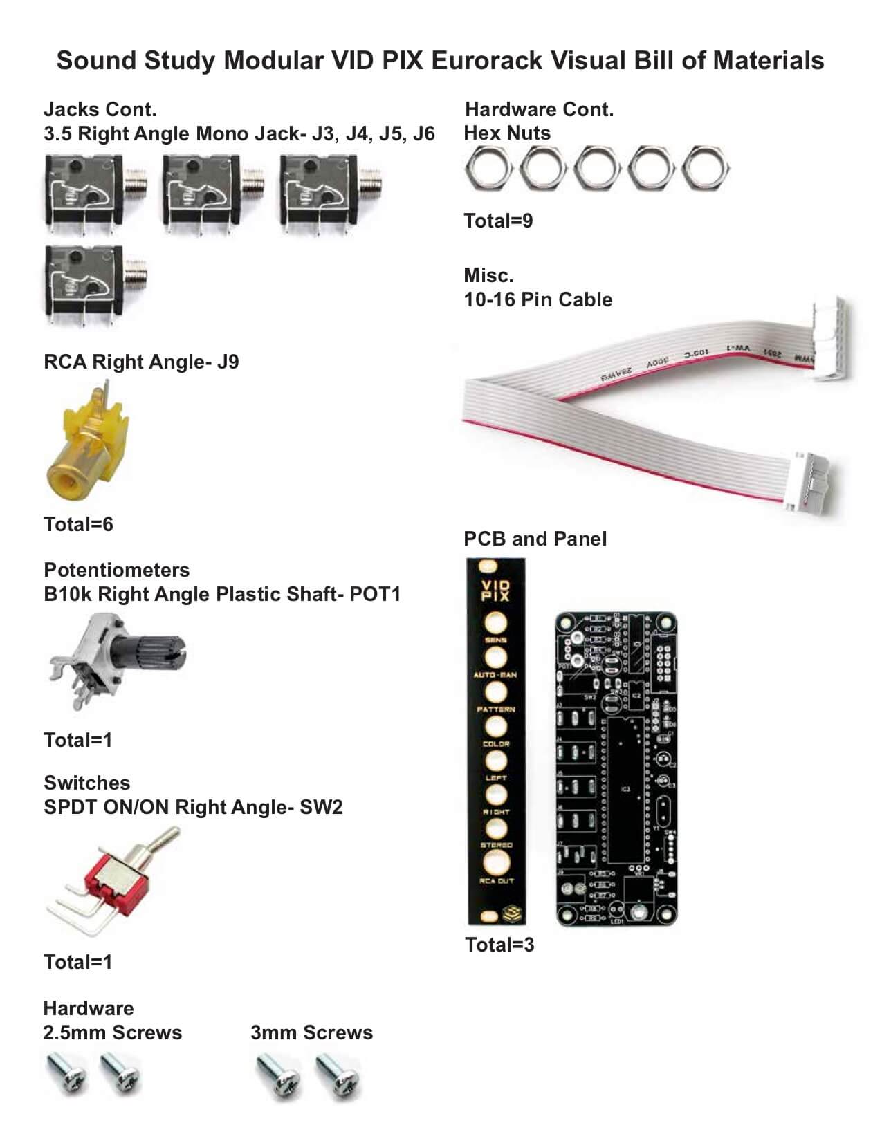
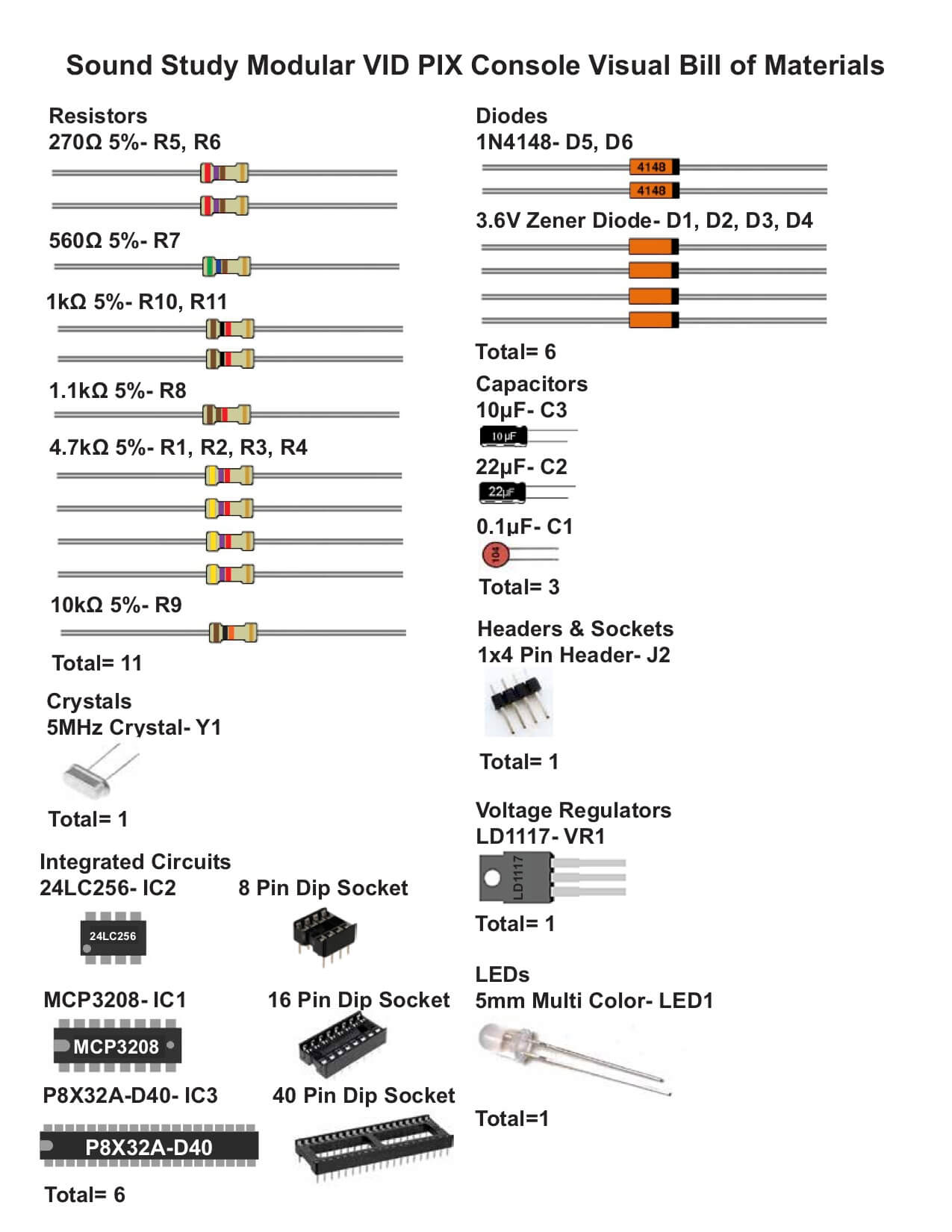
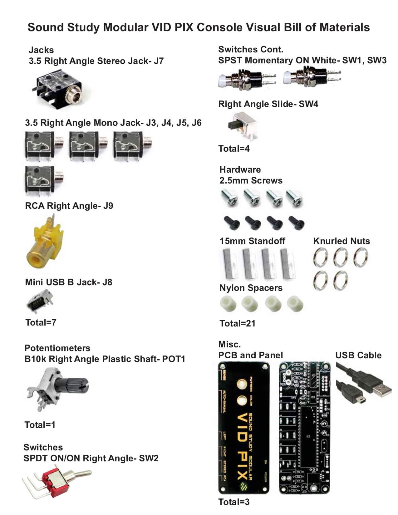
Bill of Materials
There are two versions of the Vid Pix, V1.0 and V1.2. They are functionally the same, but they have different BOMs. If you received V1.0, please use this BOM:
Eurorack V1.0 BOMs:
For a Bill of Materials with the part numbers included, click here.
Console V1.0 BOMs:
For a Bill of Materials with the part numbers included, click here.
Eurorack V1.2 BOM:
For a Bill of Materials with the part numbers included, click here.
Console V1.2 BOM:
For a Bill of Materials with the part numbers included, click here.
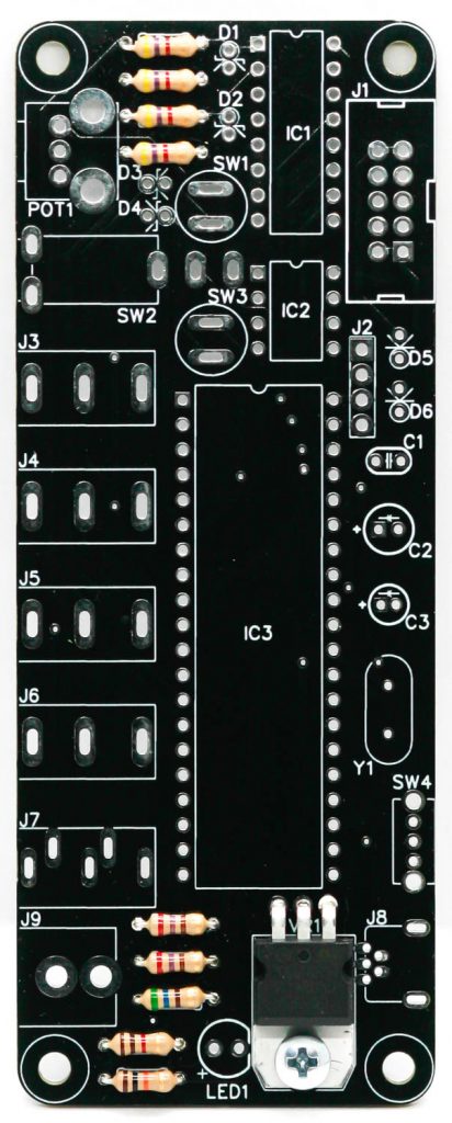
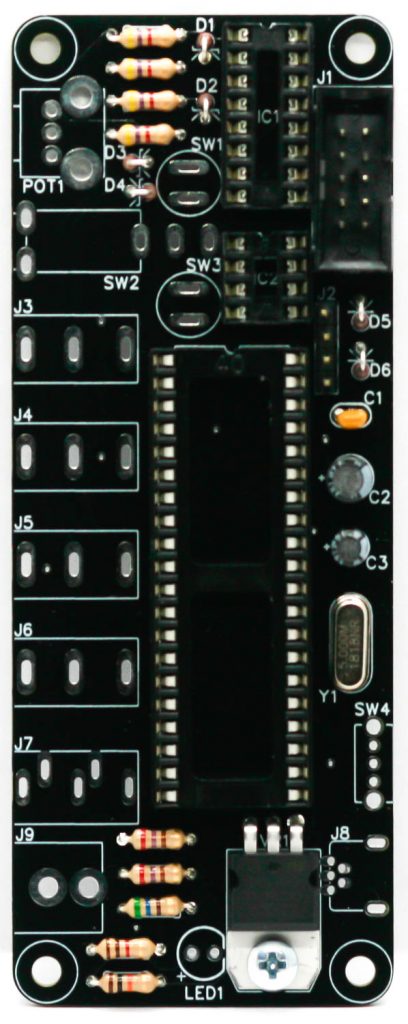
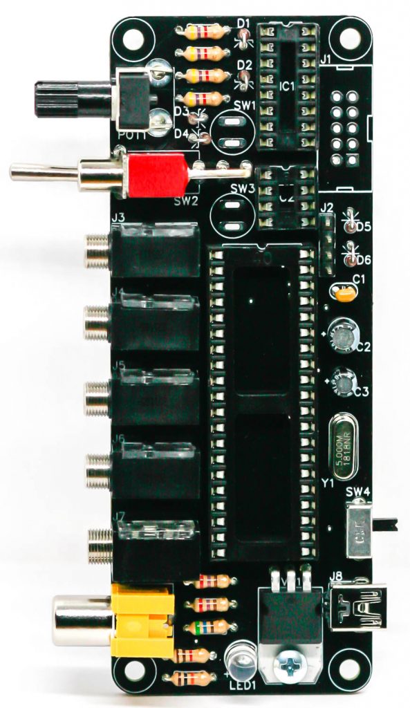
- VID PIX RESISTORS & VOLTAGE REGULATOR
The resistors are non-polarized, so it doesn’t matter which direction they go, but it makes troubleshooting much easier if they are all oriented in the same direction. Once you have them all in their correct places, you can flip over your project and solder, clipping the excess leads.
Next, add the voltage regulator as shown below. It is easier to fit in if you bend the legs with a pair of pliers first. If you were provided with an insulator, install it. If your kit didn’t come with an insulator, you don’t need one.
Note: it is not necessary to screw the voltage regulator into the board.
Flip over the PCB and trim the leads.
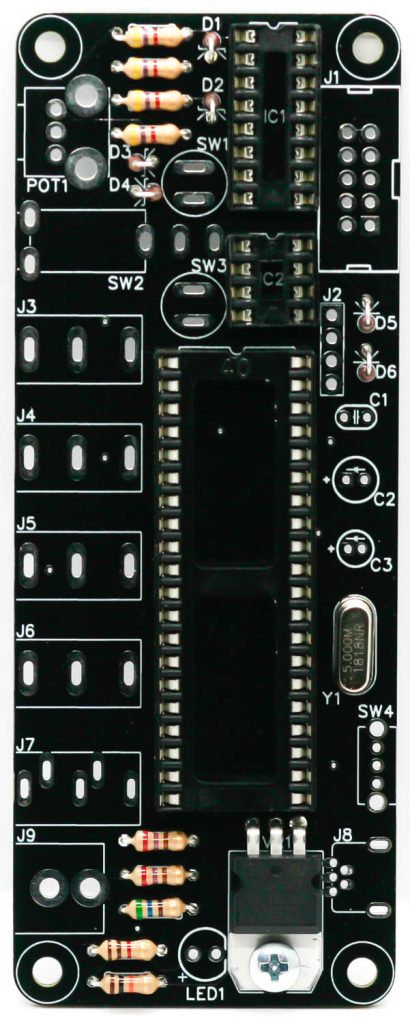
2. VID PIX CRYSTAL, SOCKETS & STAND UP DIODES
The crystal is non-polarized, so populate it in either direction. The diodes are polarized components, so make sure to line up the stripe on the diode with the stripe on the silkscreen (striped side down). It is easier to bend the diodes first before populating them into the PCB. Align the notch in the socket with the notch on the PCB silkscreen graphics. When you have them populated, flip your project over on a flat surface and solder them in place, clipping the excess leads.
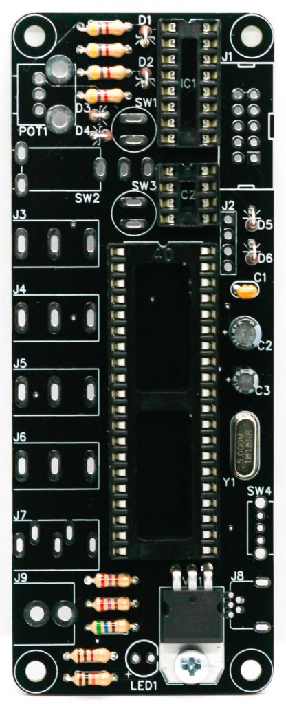
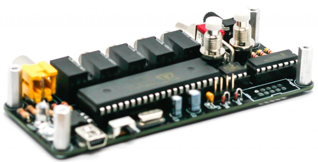
3. VID PIX CAPACITORS
Now we can populate the ceramic capacitor. These are non-polarized as well, so they can be populated in either direction, but it is recommended to place them so that the numbers written on them can be easily read. This will help if you need to troubleshoot your build later.
The electrolytic capacitors are polarized, so they must be oriented in a specific manner. When populating them, align the longer leg of the capacitor with the + symbol on the silkscreen. Once you have it correctly populated, flip your project over and solder everything in place, clipping any excess leads.
4. EURORACK 10 PIN POWER HEADER
SKIP TO STEP 5 IF ASSEMBLING THE CONSOLE VERSION
The 10 pin Eurorack power header is polarized. Align the notch in the head with the notch on the PCB silkscreen. Flip your PCB over and solder into place
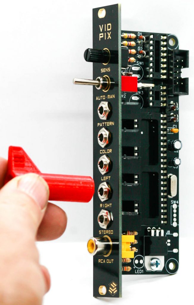
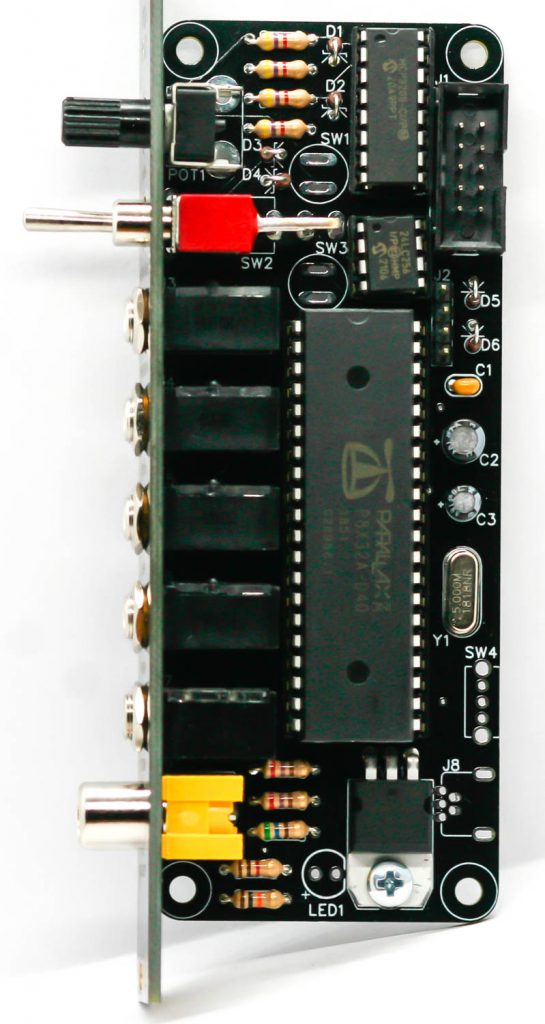
EURORACK PANEL COMPONENTS
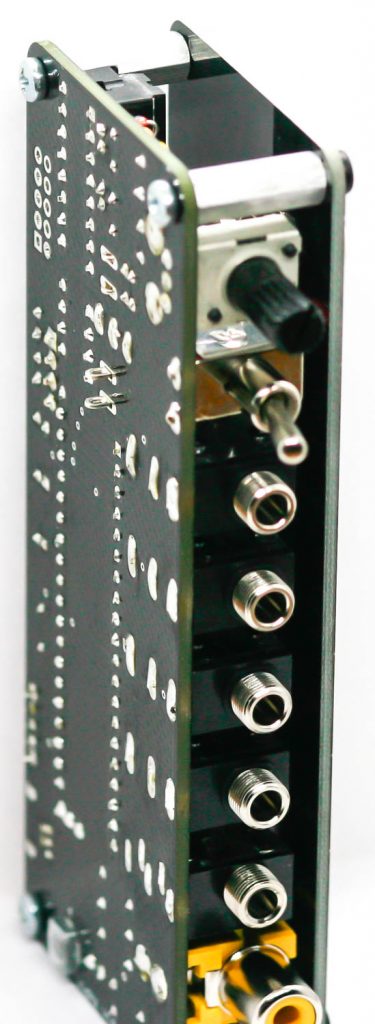
Now place the pot, switch, mono jacks, stereo jack (only fits in one place) and RCA jack into the PCB and carefully place the panel over those components. Then take the audio jack nuts and secure them down thumb-tight to the PCB. Once everything is lined up squarely, tighten the jacks a bit more, but not too much.
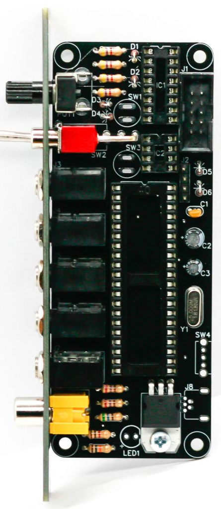
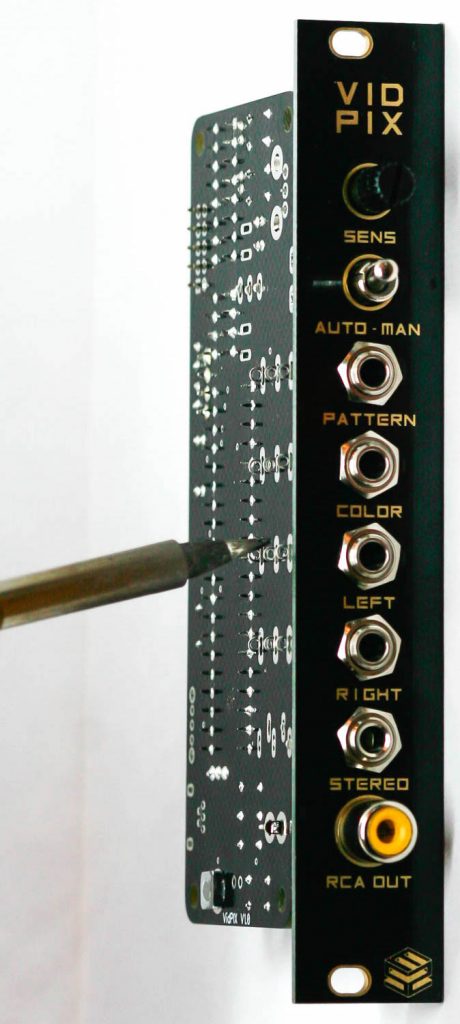
Carefully turn the PCB over and solder all of the panel components in place.
Now place the ICs into the sockets by aligning the IC’s notch with the notch on the socket.
Congrats! You can down plug your module into your Euroack power supply and television!
5. CONSOLE USB JACK & SWITCH
Place the switch and USB jacks into the PCB as shown below then turn over and carefully solder in place.
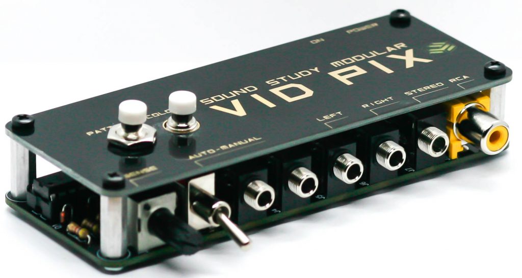
6. CONSOLE PANEL COMPONENTS
Now place the LED, pot, switch, mono jacks, stereo jack (only fits in one place) and RCA jack into the PCB and carefully turn the project over to solder the components in place. It will be easer to do the jacks first, then the pot, then the switch.
7. CONSOLE PUSHBUTTONS & STANDOFFS
Place, but do not solder just yet, the pushbuttons. Screw the standoffs onto the PCB as shown below.
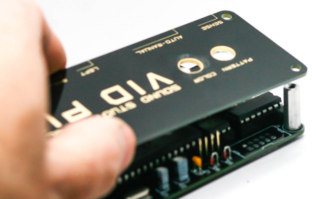
8. CONSOLE PANEL
Now place the panel over the switches and standoffs.
Add the nuts to the switches and the black screws to the standoffs through the panel
Solder the pushbuttons in place.
You are done! Time to now plug your unit into power via the USB jack and connect your TV via the RCA jack.