Important Links
Product Page
Store Page
Assembly Instructions
QC Instructions
Bill of Materials
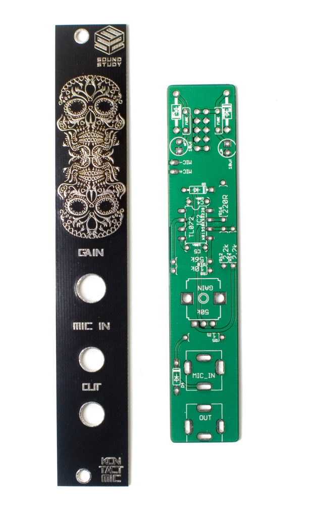
Kontact MIC Assembly Instructions
Thank you for purchasing the Sound Study Modular Kontact MIC kit!
ATTN: Please follow the BOM and these instructions. Don’t populate from the PCB silkscreen or these instruction pictures alone. Our components may look different from the pictures, so please look over your parts and check the codes first.
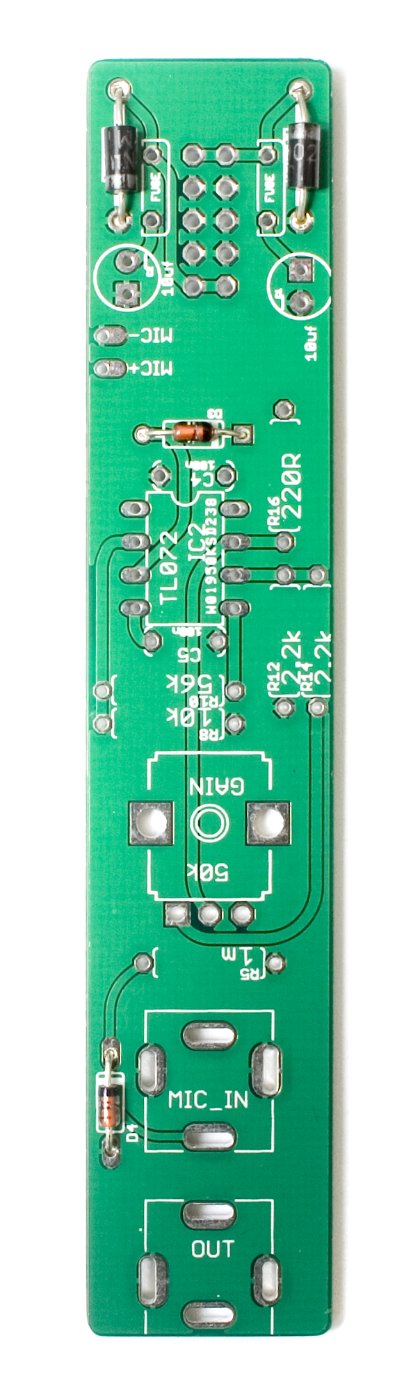
 Diodes

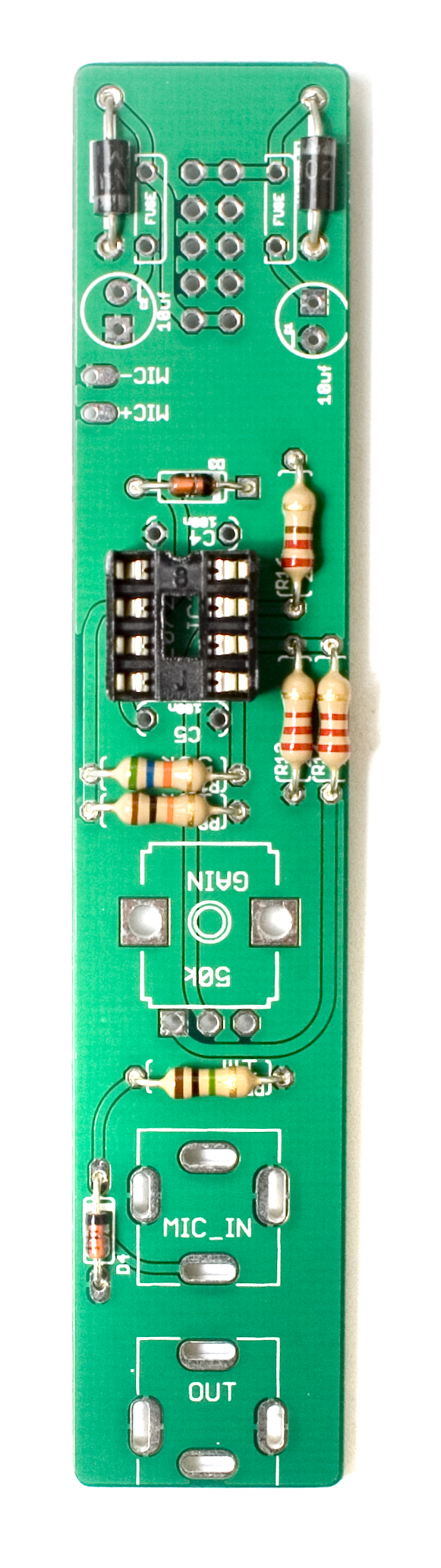
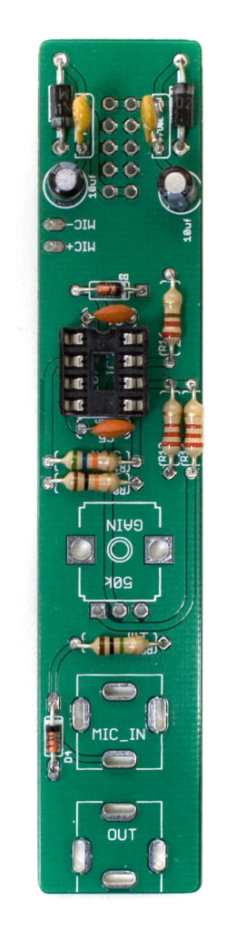
First up are the diodes. There are two little orange diodes and two larger black ones, so make sure that you pay attention to the BOM when populating these. Diodes are polarized, so when inserting them into the PCB, make sure that you align the cathode band (stripe) on the diode with the cathode band on the PCB. Once you have them in, carefully flip your project over, and solder everything in place, clipping any excess leads.
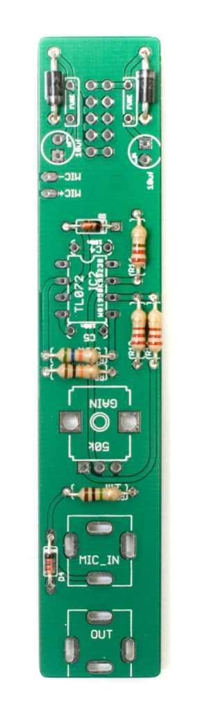
 Resistors
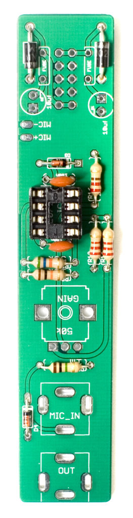
Now we can populate the resistors. These are non polarized so it does not matter which way you insert them into the PCB. If you align them all so that the tolerance bands (usually a gold stripe) all face the same side, then any troubleshooting you may need to do later would be much easier. Once you have them populated in the proper spots as per the BOM, carefully flip your project over and solder them into place, clipping any excess leads.
 IC Socket

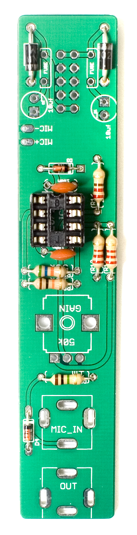
Next up is the IC socket. These sockets have a semicircular notch in one side to indicate where pin one is. Ensure that you align this notch with the same notch on the PCB. This will help ensure that you insert the IC correctly. Once its in there properly, flip the project over and solder in place. A trick to get these to sit flat is to only solder one leg to start, and then while applying gentle pressure, re heat the pin that you soldered and pushing it flat against the board.
 Ceramic Capacitors
Next we can populate the ceramic capacitors. The ceramic capacitors are non-polar, so you can populate them any direction you would like, but we recommend installing them in a way that makes them easy to read once everything else is installed. Once everything is in, flip your project over, solder everything in place, and clip any excess leads. You may want to use the help of a piece of plastic or cardboard to help you flip the project over so that nothing falls out while doing so.
 Electrolytic Capacitors
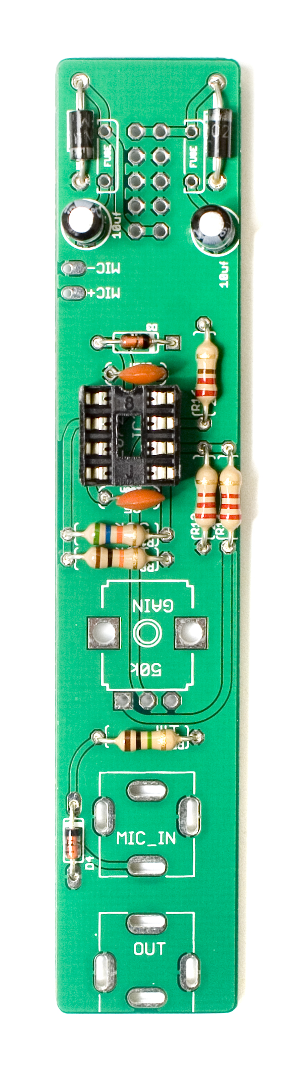
Now we can populate the electrolytic capacitors. The electrolytic capacitors are polarized, so take care when populating them to make the stripe (cathode) line up with the minus sign on the PCB.
Once everything is in, flip your project over, solder everything in place, and clip any excess leads. You may want to use the help of a piece of plastic or cardboard to help you flip the project over so that nothing falls out while doing so.
 Fuses
Fuses
Next up are the resettable fuses. These guys are going to stick up pretty far, but insert them into the PCB as far as they can go, without pushing too hard. They aren’t polarized, so it does not matter which direction you orient them in. Once populated, carefully flip the project over and solder them in place, clipping excess leads.
 Power Header

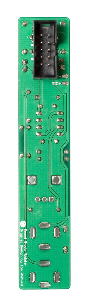
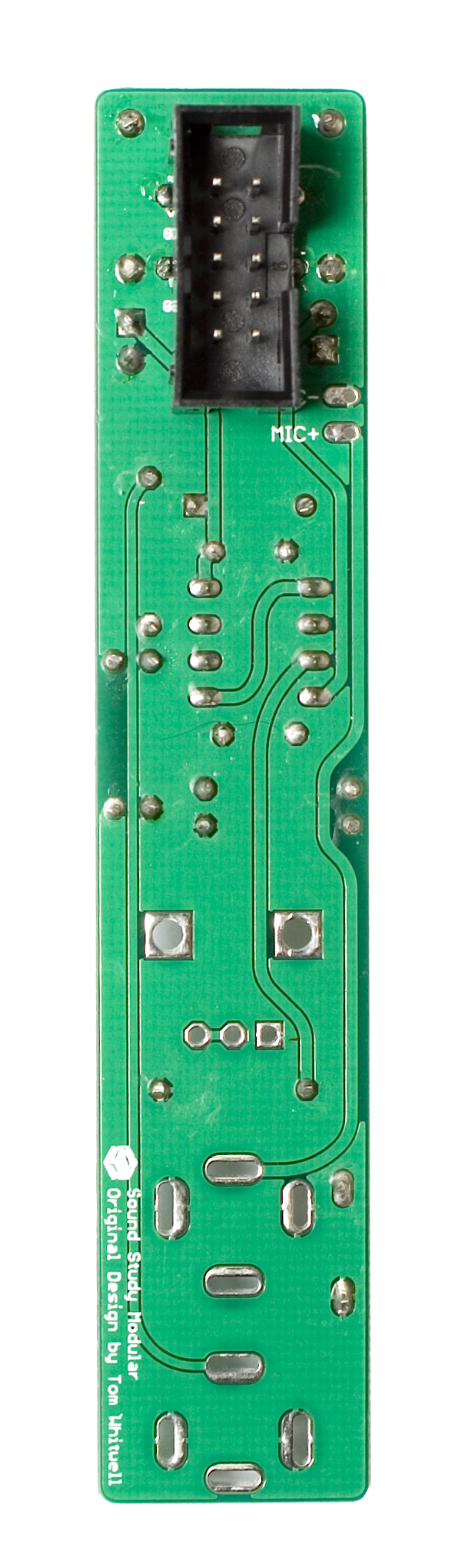
Next up is the 10 pin power header. Make sure when you are populating this that you align the notch in the header to the right when the stripe indicator that is printed on the PCB is down. Please look carefully at the picture below and make sure yours looks just like it.
When you are sure its oriented properly, go ahead and solder it in place.
 Piezo Mic Prep
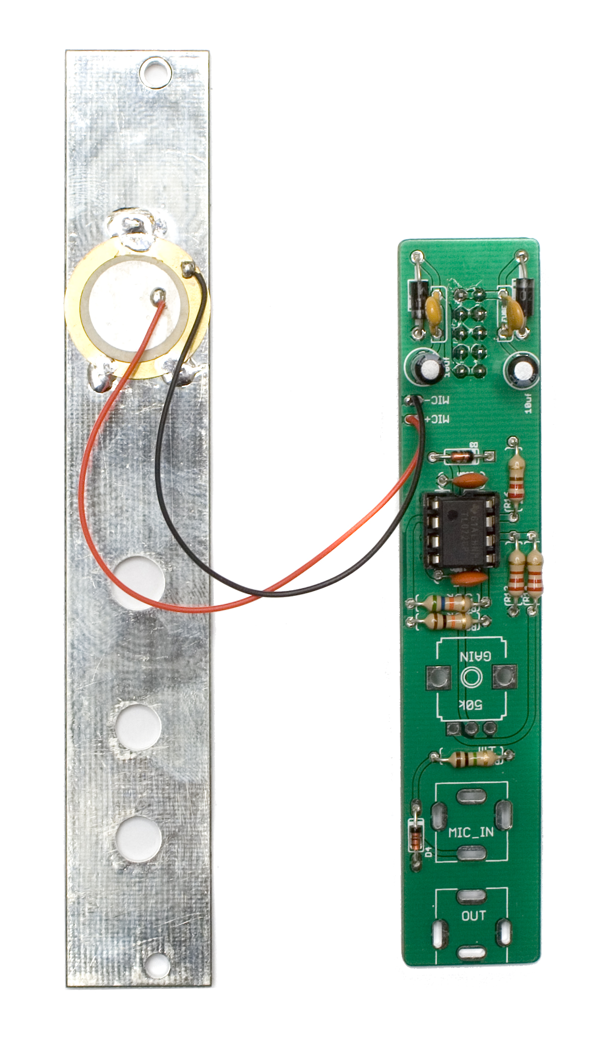
Next, we are going to solder the piezo mic to the back of the front panel. Make sure that you align the piezo around the middle of the graphic on the front. Start by soldering just the top part of the piezo, and then gently apply pressure to the sides while re heating the solder point to align the piezo horizontally behind the panel. If the piezo sticks out a little bit, you can either bend it over, or take some clippers and trim a little bit of the metal disc so that it doesn’t stick out from the side of the panel. Once it is nice and straight, you can solder the other two points on the piezo.
 Connecting the Piezo to the PCB
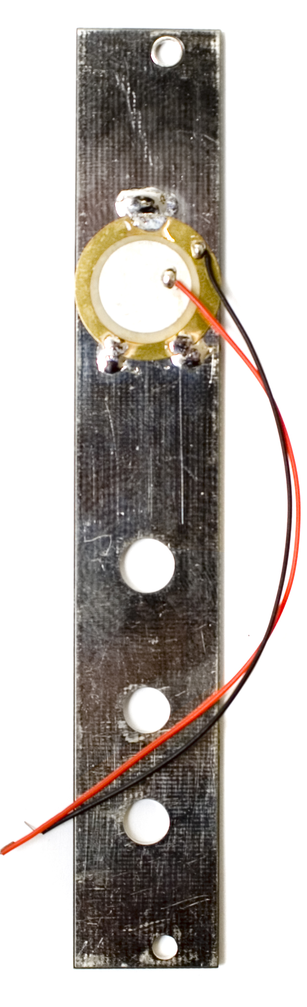
Next, take the red wire from the piezo and solder it into the spot marked MIC+ on the PCB, and solder the black wire to the spot marked MIC- on the PCB.
 Potentiometer and Jacks
Next, insert the potentiometer and jacks into the PCB, making sure that the jacks are oriented properly. They should go into place easily, and will be ‘facing’ each other.
DO NOT SOLDER ANYTHING YET
Placing the front panel
Now carefully place the front panel onto the PCB, making sure to get all the components flat on the PCB.
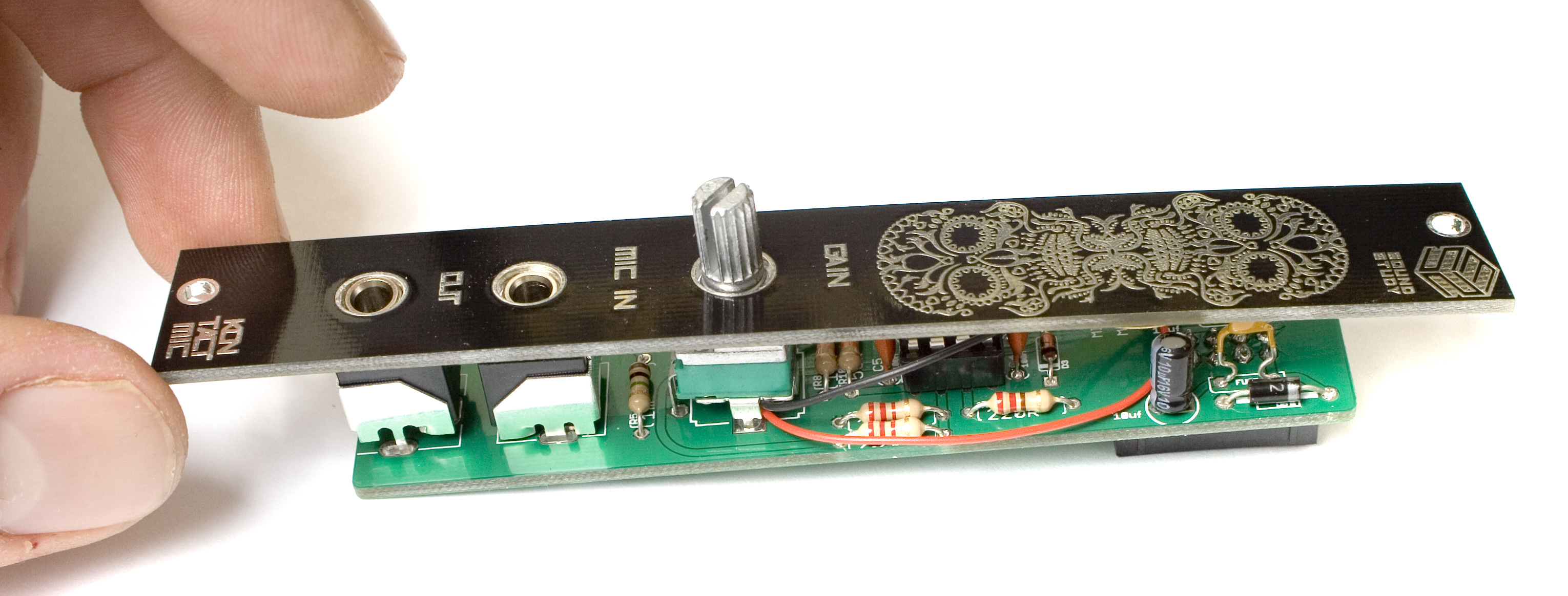
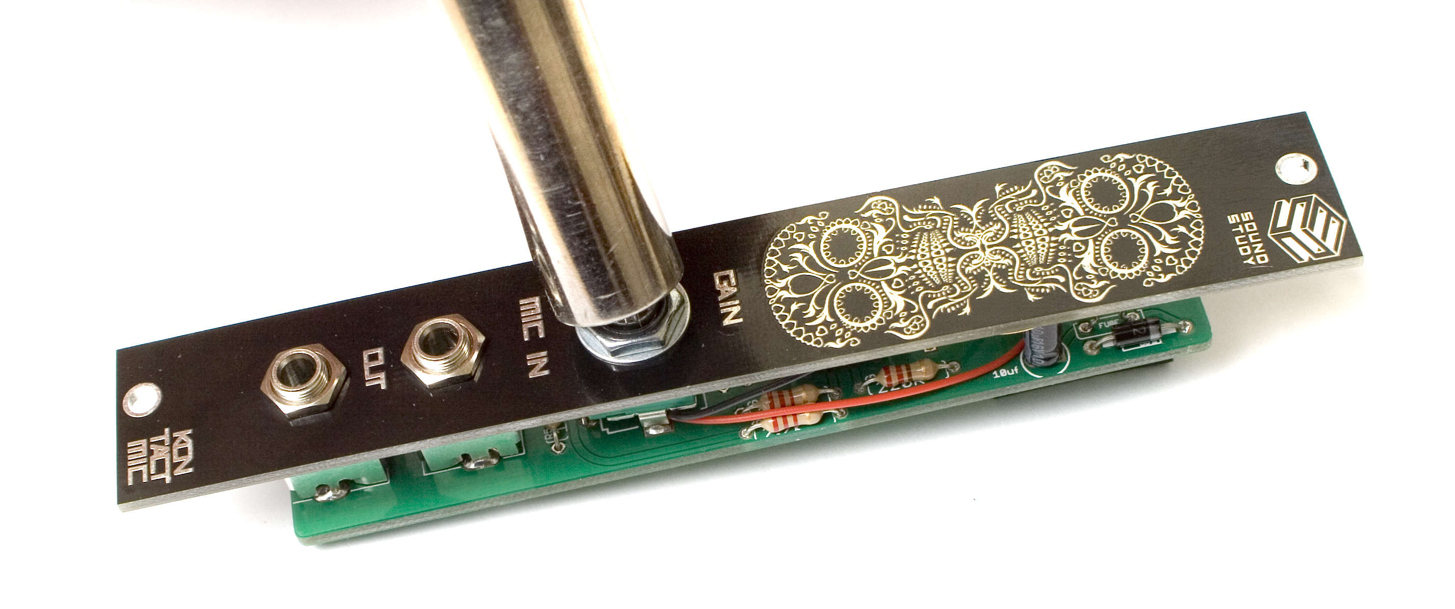
Next, put on the nuts, and tighten them all snug down with a tool. (DONT OVERTIGHTEN)
Make sure that the two boards are parallel, and that all the jacks and the potentiometer are sitting flush with both the panel, and the PCB. Once it all is flat, solder everything in place.
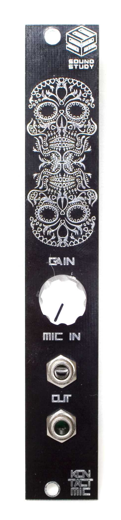
Then just install the knob on the knurled part of the potentiometer shaft, and you should be done. Time to go plug it in and try it out!
QC Instructions
Below are the procedures that we follow to ensure that our Kontact MIC units are working properly.
First, run a patch cable from the Kontact MIC’s OUT jack, and run it into your output mixer. When you tap on the sugar skull graphic, you should hear that tapping at the output mixer. By turning up the Gain knob, the tapping sound from the Kontact MIC should get louder.
There are a couple ways to check the MIC IN jack. The MIC IN is basically just an amplifier, so it can take whatever signal you give it, and then spits it out amplified. (according to where the GAIN knob is set.)
The easiest way to test the MIC IN, is to plug a set of headphones into it, then speak into the earpiece of the headphones. You should hear your voice coming out of the output mixer, amplified according to where you have the GAIN knob set.