Important note: This is a guide to assembling our finish-it-yourself kit. The SMD parts are already populated, and the firmware is pre-programmed.
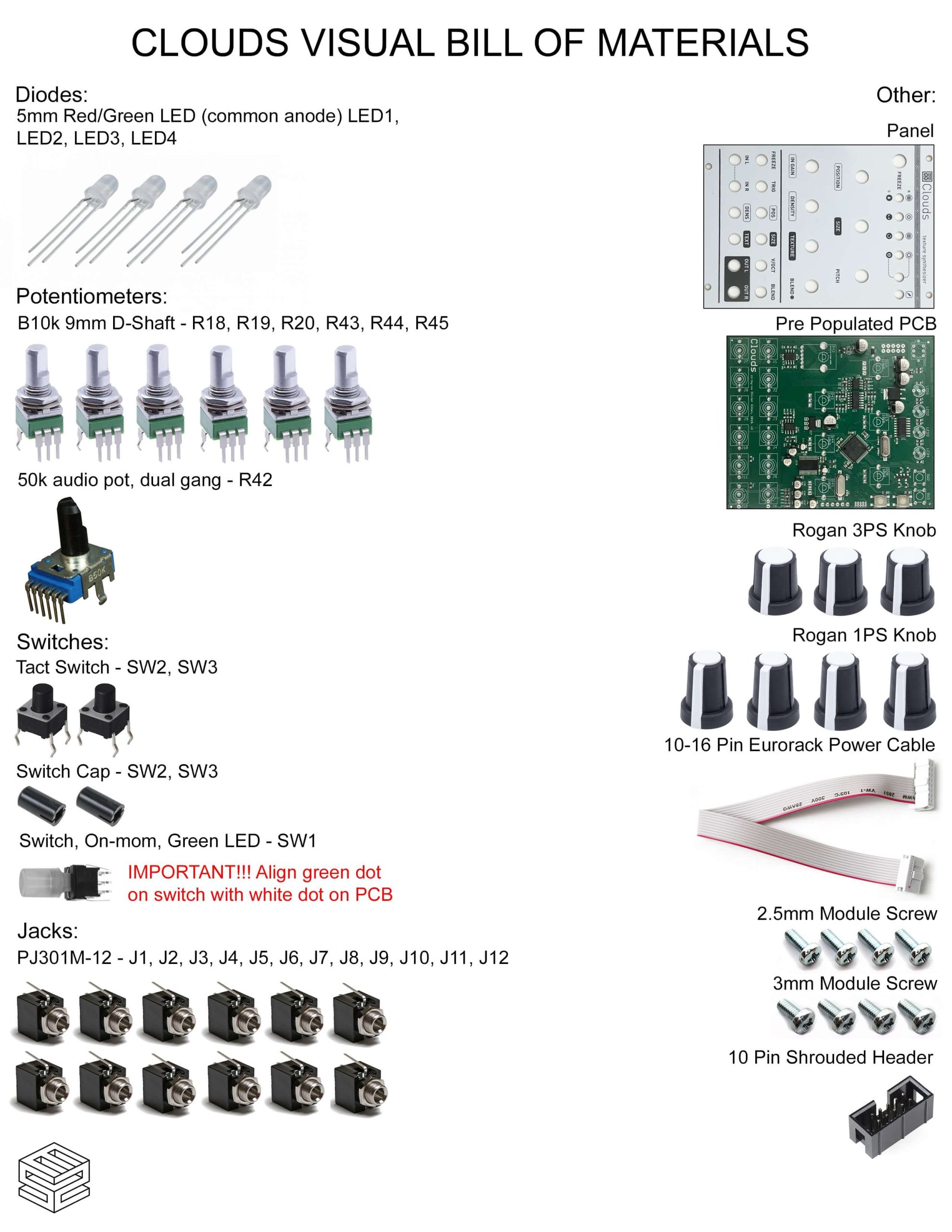
Click here for a bill of materials with Mouser part numbers.
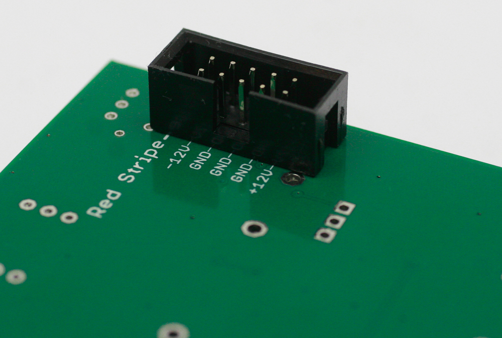
10 Pin Power Header
Our kit includes a keyed power header. Place the header on the rear of the board exactly as shown below, with the notch facing towards the text. Carefully turn the project over to solder in place.
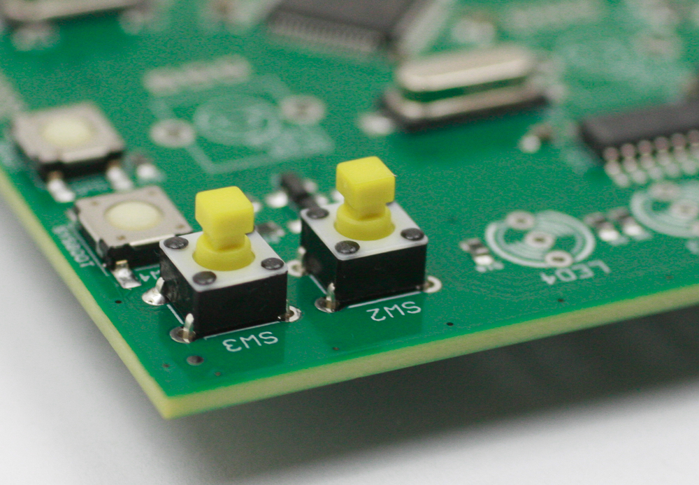
TACT SWITCHES
Place the two tact switches into the PCB as shown below, then carefully turn the project over to solder them in place.
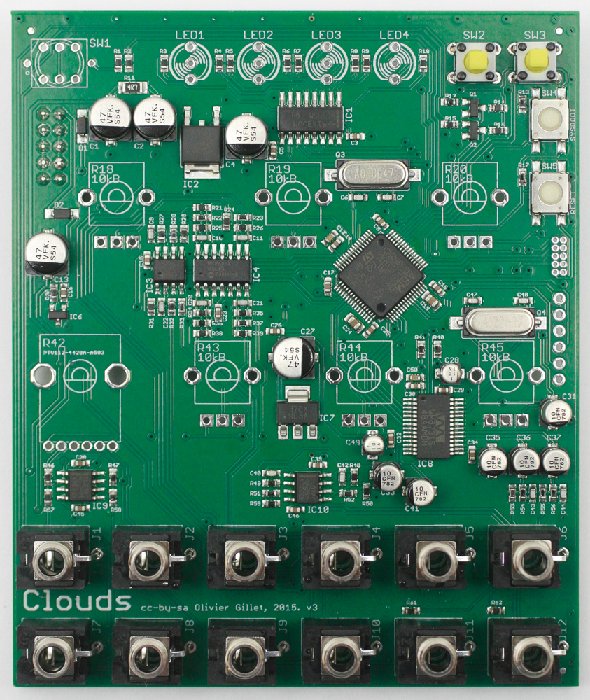
Jacks
Place the jacks into the PCB as shown below. Carefully turn the project over to solder in place. You can use the panel to make sure that the jacks all stay in place.
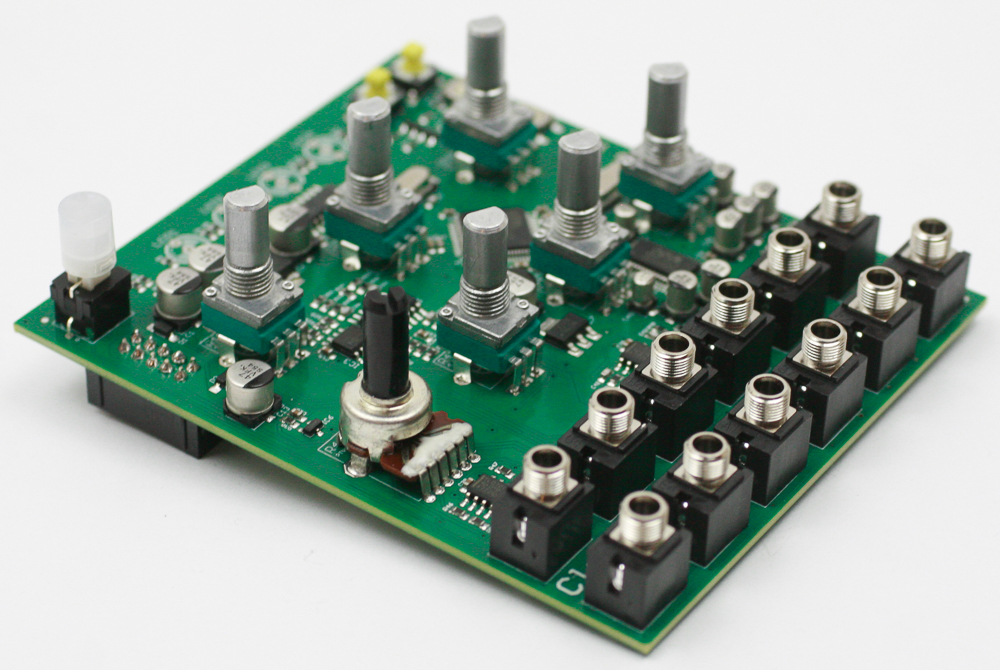
Potentiometers and LED Switch
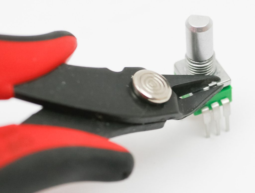
If your pots have a tab (like the one below), make sure to trim them before assembly.
Place all of the pots into the PCB as shown below.
Insert the LED switch, orienting the dot on the switch to the dot on the PCB.
Don’t solder these components just yet.
LEDs
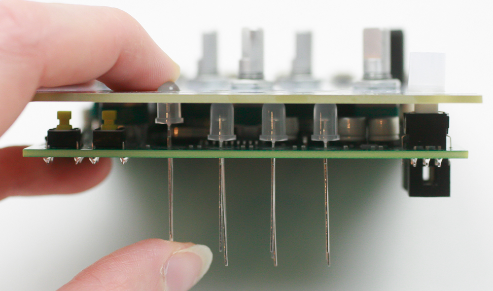
First place the front panel over the project and finger-tighten the jack, pot nuts on to the project. Place the LEDs into the project by matching the flat side of the LED with the flat side of the LED.
Press the LED through the panel as shown below. You can put a piece of masking tape over the panel over the LED holes, this helps to keep them at the same height. Before soldering one of the LED legs, load up a bit of solder on the soldering iron tip then tack one leg in. Do this for the remaining LEDs.
You can now also solder the pots, LED switch, and jacks (if you haven’t already).
Once the LEDs are in place, clip the the excess leads.
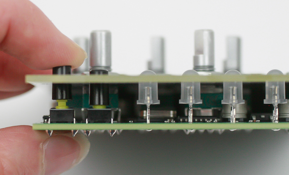
Tact Switch Caps
Tightly press the tact switch caps on to the tact switches as shown below.
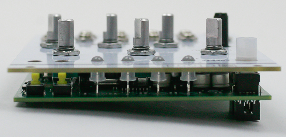
Knobs
You can now gently tighten up the nuts and then place the knobs into the PCB as shown below and firmly press them in place. Notice that the three larger knobs are for the top row.

Congrats! We’ve already programmed the firmware, so make sure the basic functions are working, and then move to the calibration below.
V/OCT Calibration Procedure
- Disconnect all CV inputs.
- Connect the note CV output of a well-calibrated keyboard interface or MIDI-CV converter to the V/OCT input.
- Hold down the top right button, and while you hold it down, quickly press the the button next to it. The first 2 LEDs will blink continuously in orange.
- Play a C2 note, or send a 1V voltage from your CV source.
- Press the top right button. The four LEDs will blink in orange.
- Play a C4 note, or send a 3V voltage from your CV source.
- Press the top right button. Calibration is done!