Important note: This is a guide to assembling our finish-it-yourself kit. The SMD parts are already populated, and the firmware is pre-programmed.
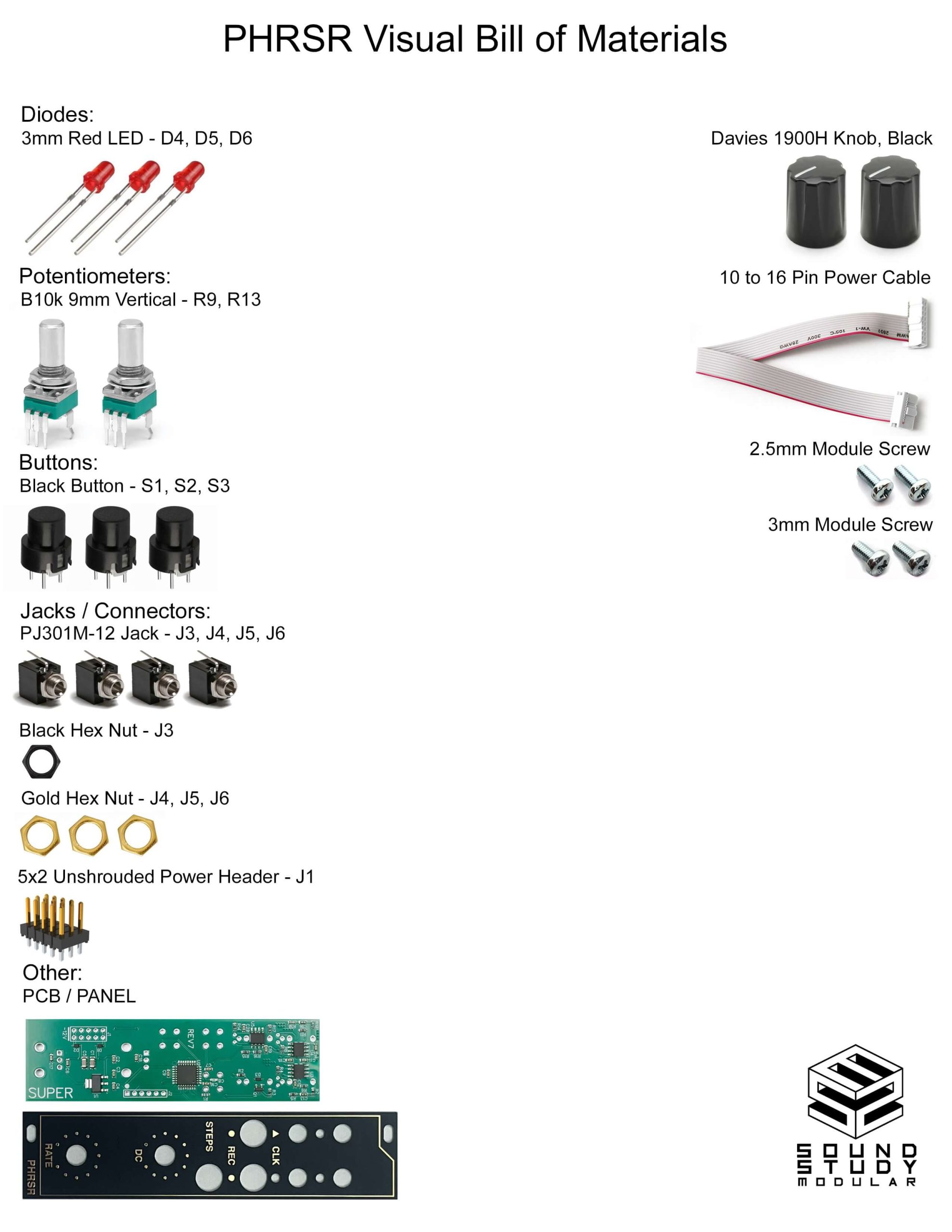
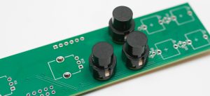
Switches
First align the flat slide of the switches with the flat side of the silk screen indicator. Insert switches into PCB (you can use the panel to help guide the spacing), carefully turn over to solder in place.
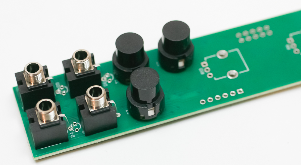
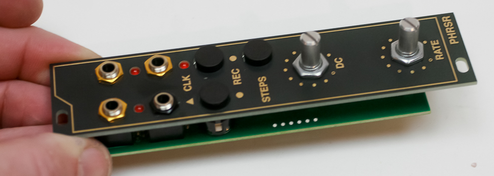
Jacks
Place the jacks into the PCB as shown below. Carefully turn the project over (again, you can use the panel to help) and solder the jacks in place.
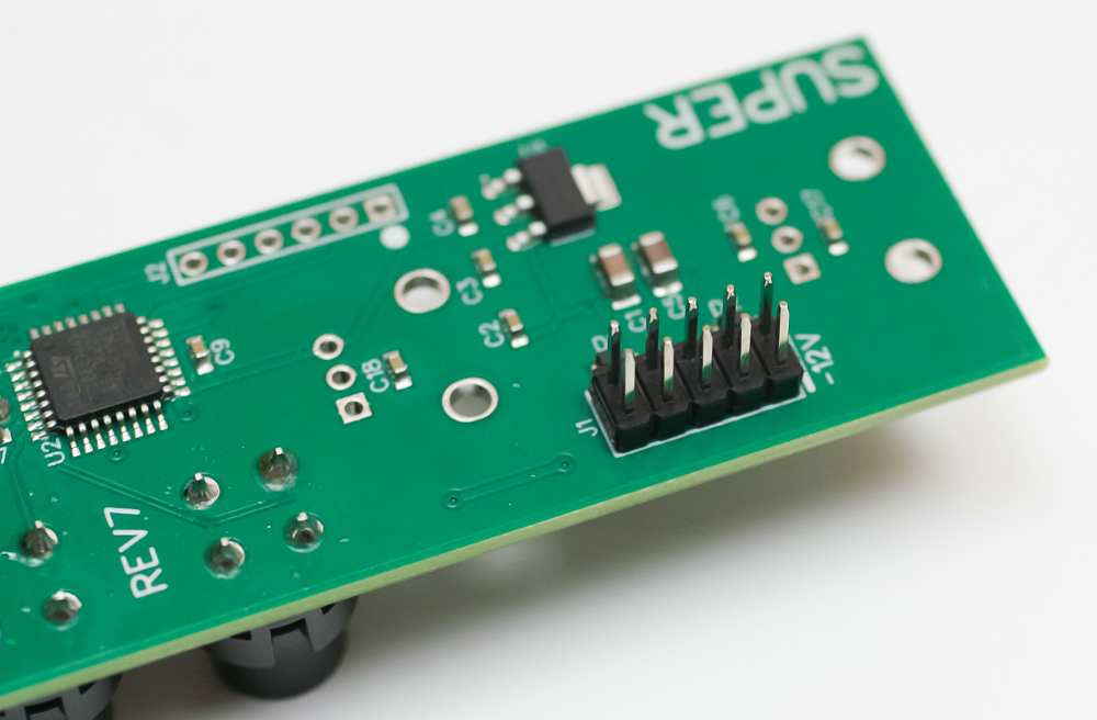
Power Header
On the opposite side of the PCB, place the power header into the PCB as shown below. Carefully turn the project over and solder in place.
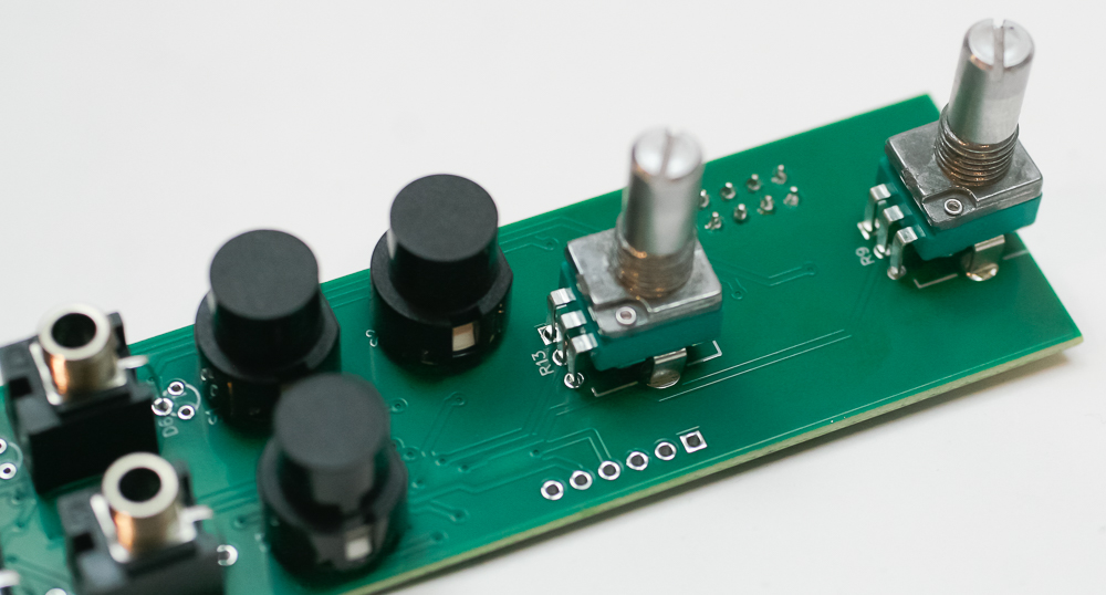
Potentiometers
Place the two pots into the PCB as shown below, then turn over to solder in place.
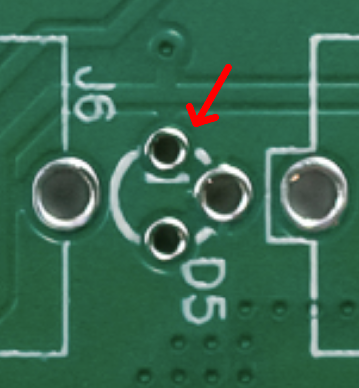
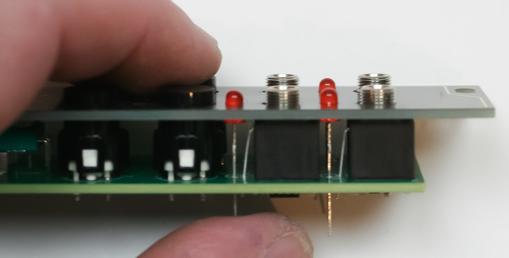
LEDs
LEDs are polarized. You can see a tiny flat line in the silk screen partially obscured by the hole. This hole is where the cathode (or negative or shorter lead of the LED) goes. Double check before you solder anything. For now, just place the LED into the PCB and DO NOT SOLDER.
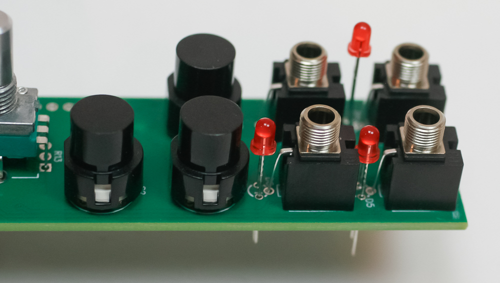
Place the panel over the project and push the LEDs through the panel to your desired depth. Carefully turn over to solder in place.
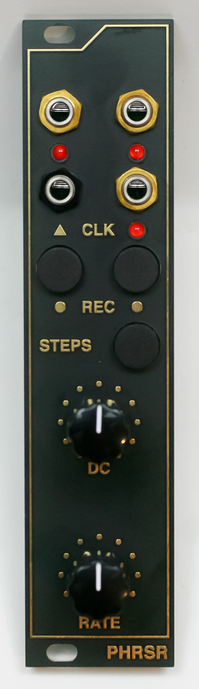
Panel Placement
You can now add the gold and black nuts to the jacks and the nuts to the potentiometers as shown below. Follow with the knobs and you are ready to test your module!
Congrats!