Important note: This is a guide to assembling our finish-it-yourself kit. The SMD parts are already populated, and the firmware is pre-programmed.
Click here for a bill of materials with Mouser part numbers.
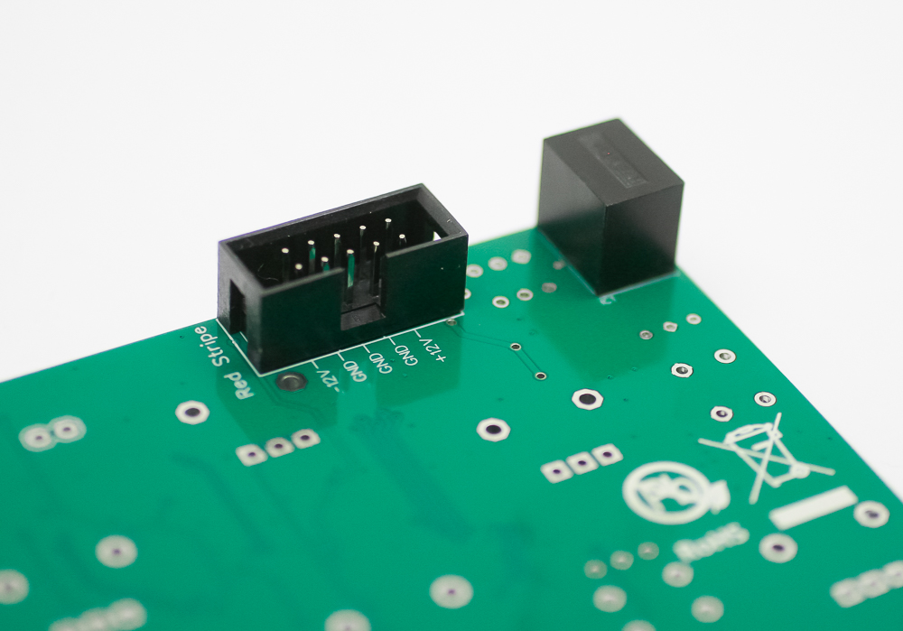
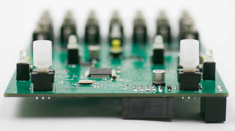
HEADER AND VOLTAGE REGULATOR
Place the 10-pin power header on the rear of the board exactly as shown below, with the notch facing down. Carefully turn over and solder in place.
Place the voltage regulator on the back side of the PCB so that it lines up with the corner of the PCB (as in the picture below). Carefully turn over and solder in place.
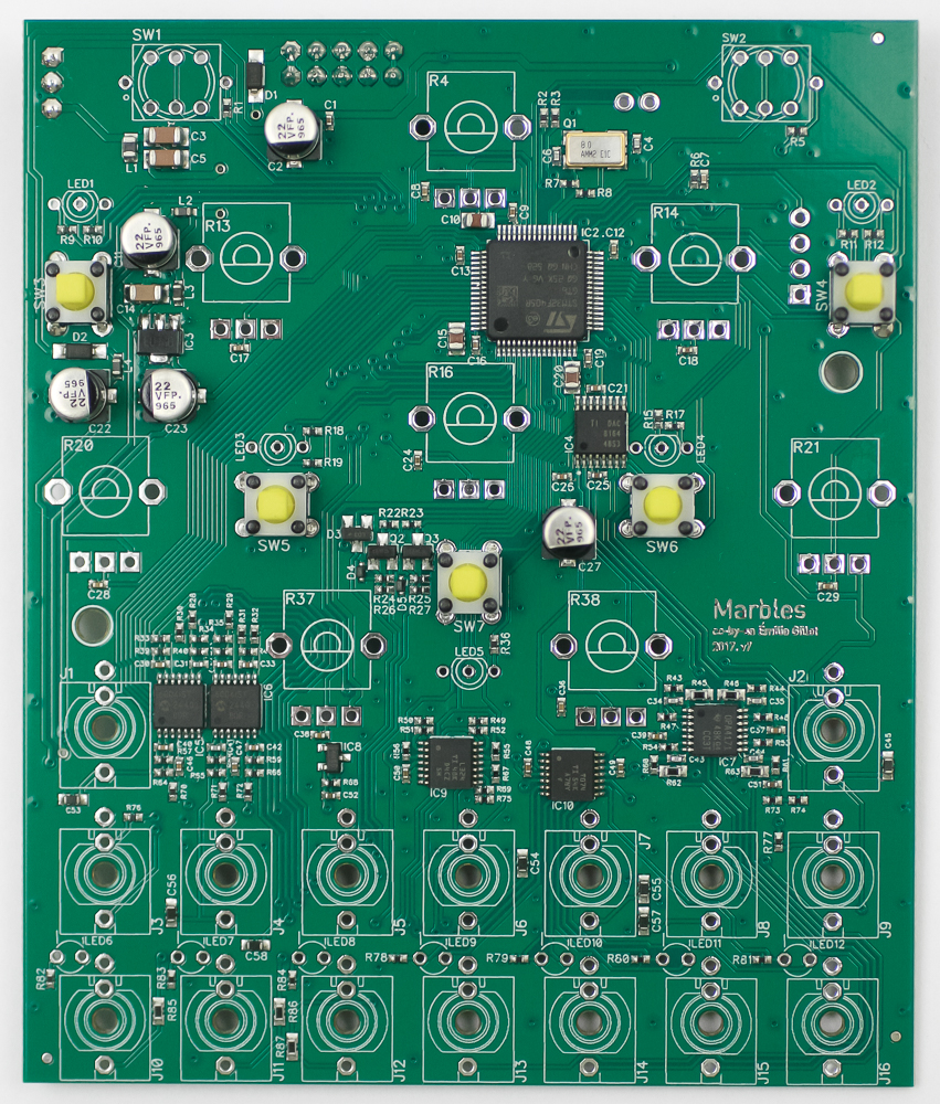
TACT SWITCHES
Place the tact switches into the PCB as shown below, then carefully turn the project over to solder them in place.
LEDs
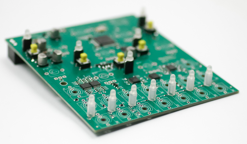
First, slip the LED spacers on all of the LEDs. The white spacers fit the 2-pin LEDs; the black spacers fit the 3-pin LEDs.
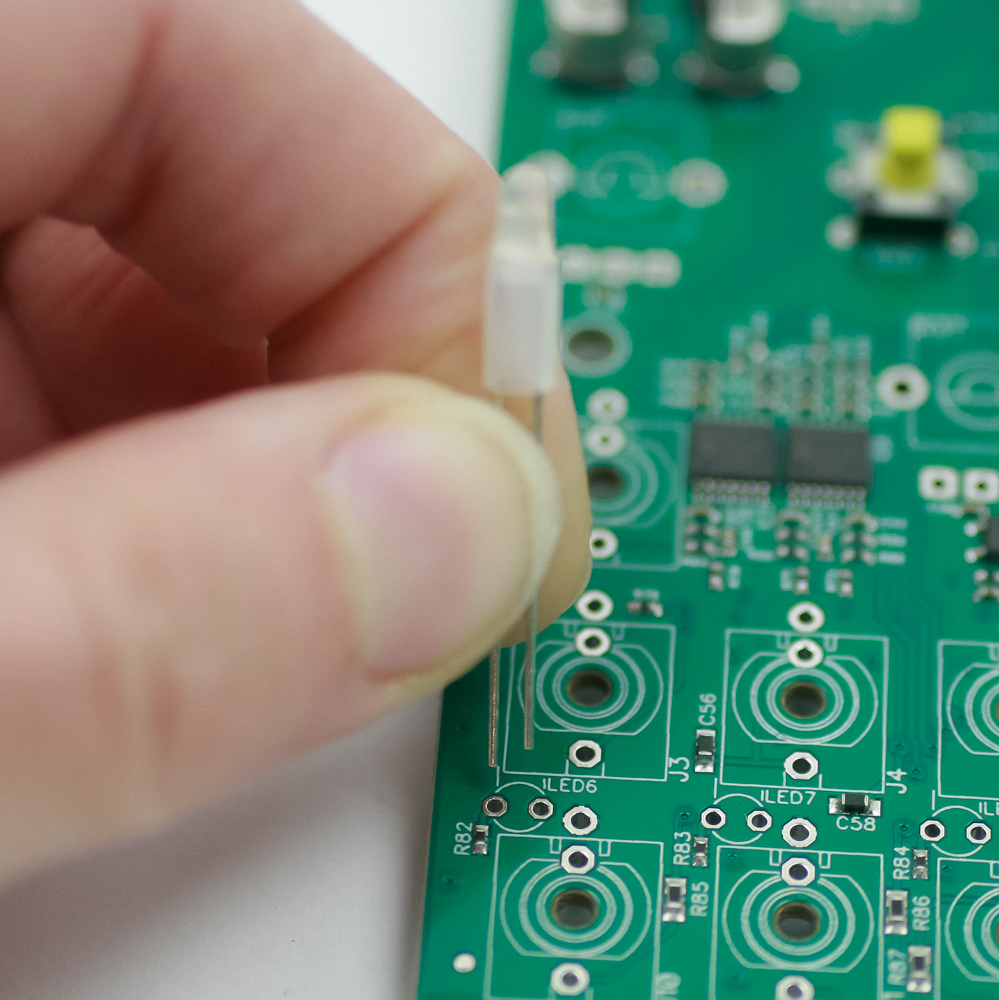
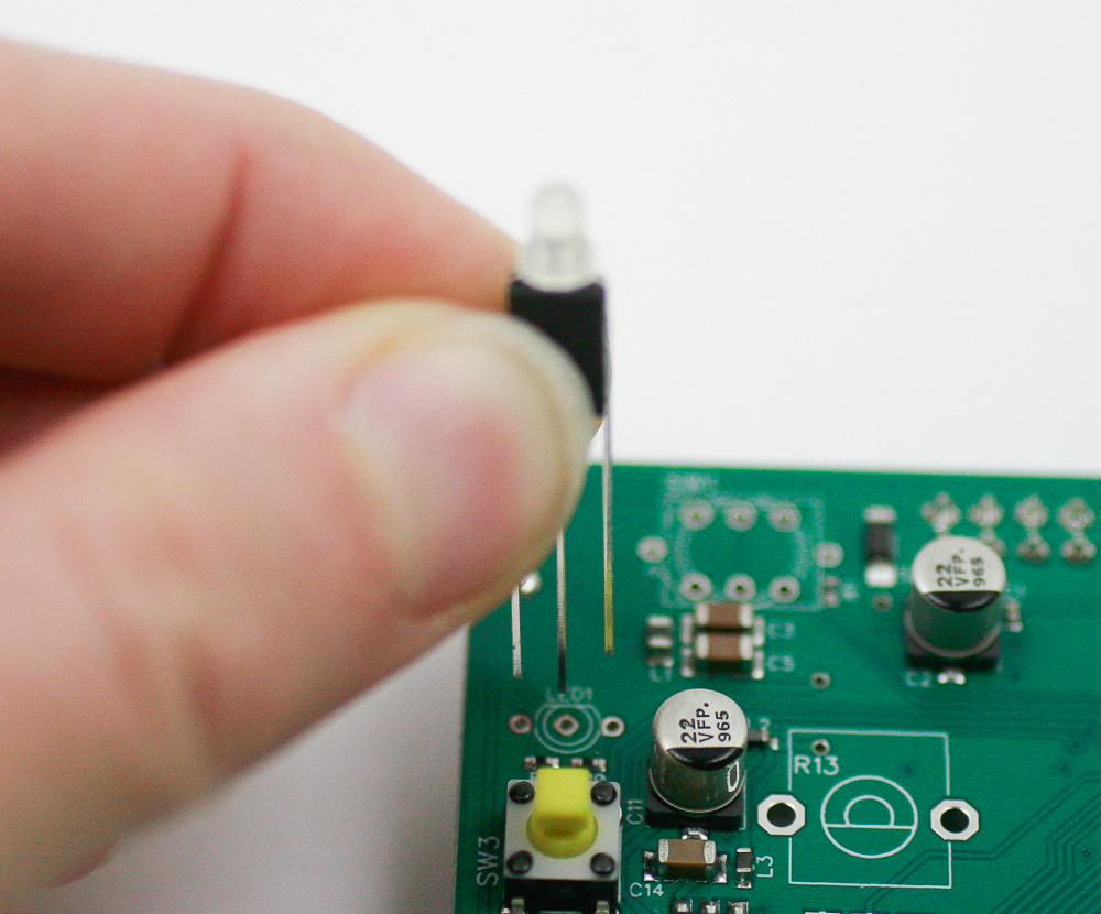
Now place the LEDs into the PCB by aligning the flat edge of the LED with the flat edge on the PCB silkscreen. Carefully turn over to solder in place. Clip excess leads.
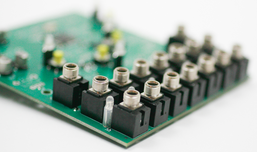
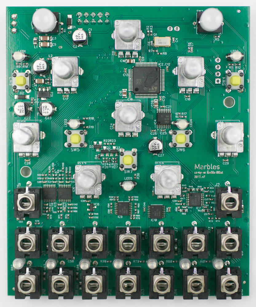
Jacks
Place the jacks into the PCB as shown below. Carefully turn the project over to solder in place. You can use the panel to make sure that the jacks all stay in place.
Push Button Switches
Carefully place the LED push button switches into the PCB as shown below. Make sure to align the green dot on the switch with the white dot on the silkscreen.
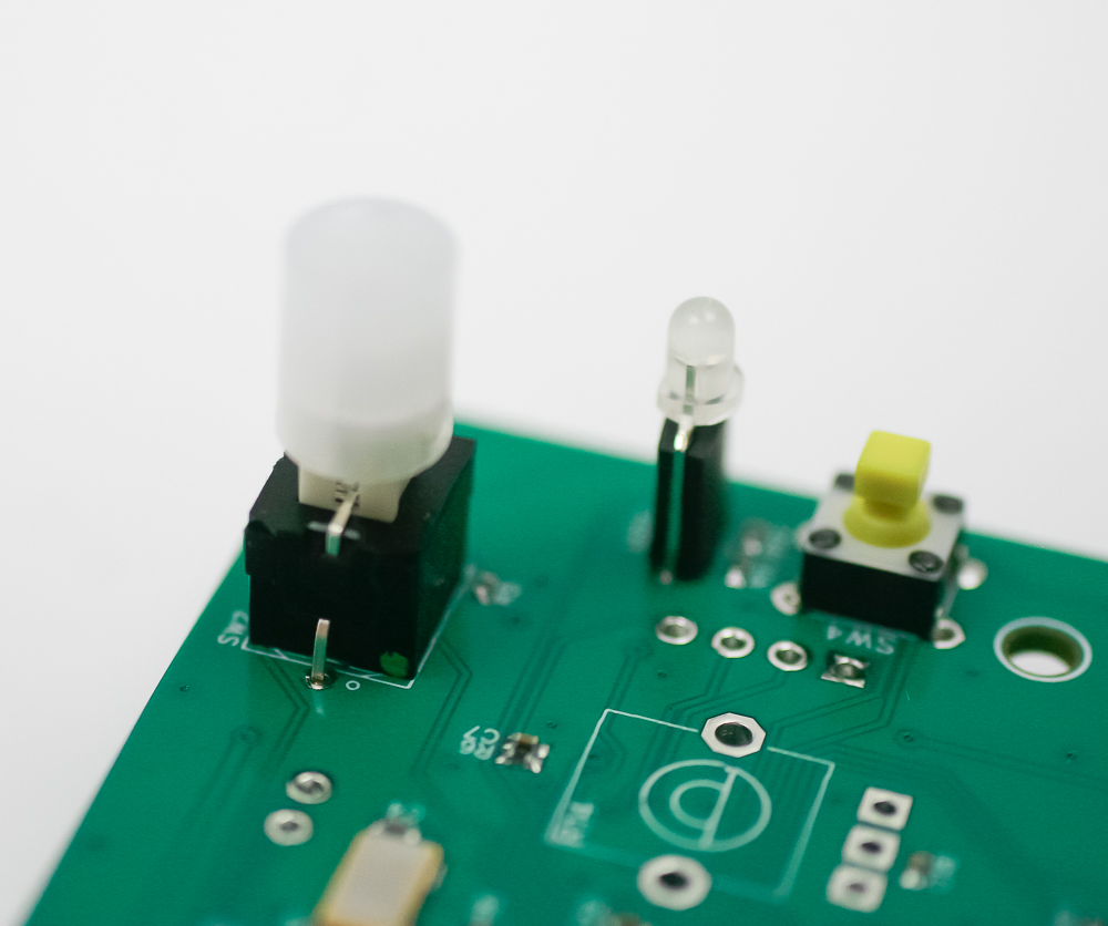
Carefully turn the project over to solder in place.
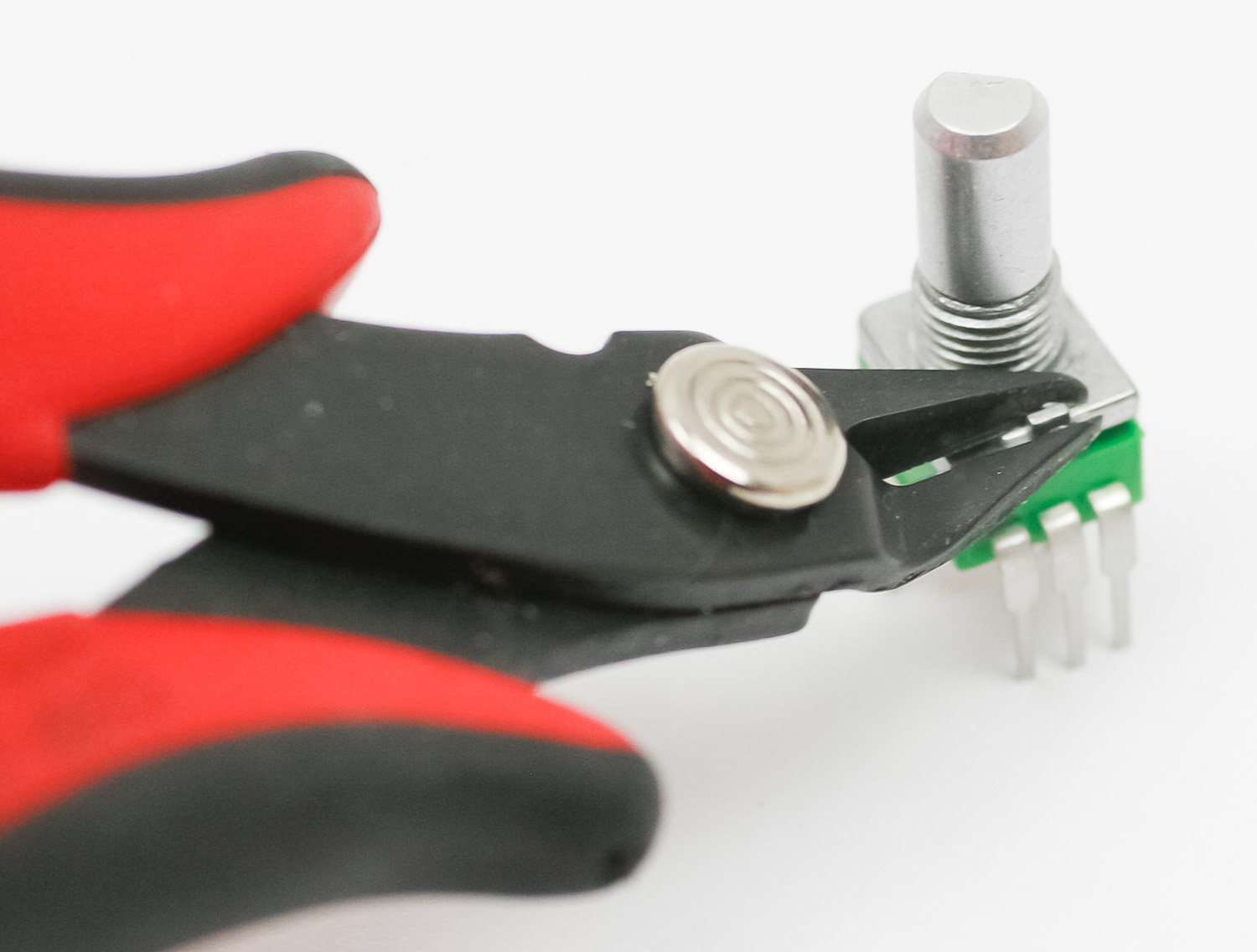
Potentiometers
if your pots have a tab (like the one below), make sure to clip it before assembly.
Place all of the pots into the PCB as shown below. Carefully turn the project over to solder in place. You can use the panel to make sure that the pots all stay in place.
Tact Switch Caps
Tightly press the tact switch caps on to the tact switches as shown below.
Panel
Carefully place the panel over your components as shown below. Take your time to make sure the LEDs don’t bend over.
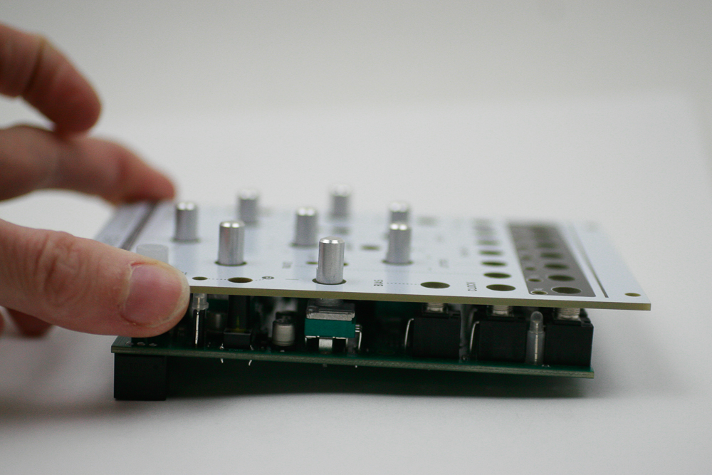
Now gently tighten the jack and pot nuts.
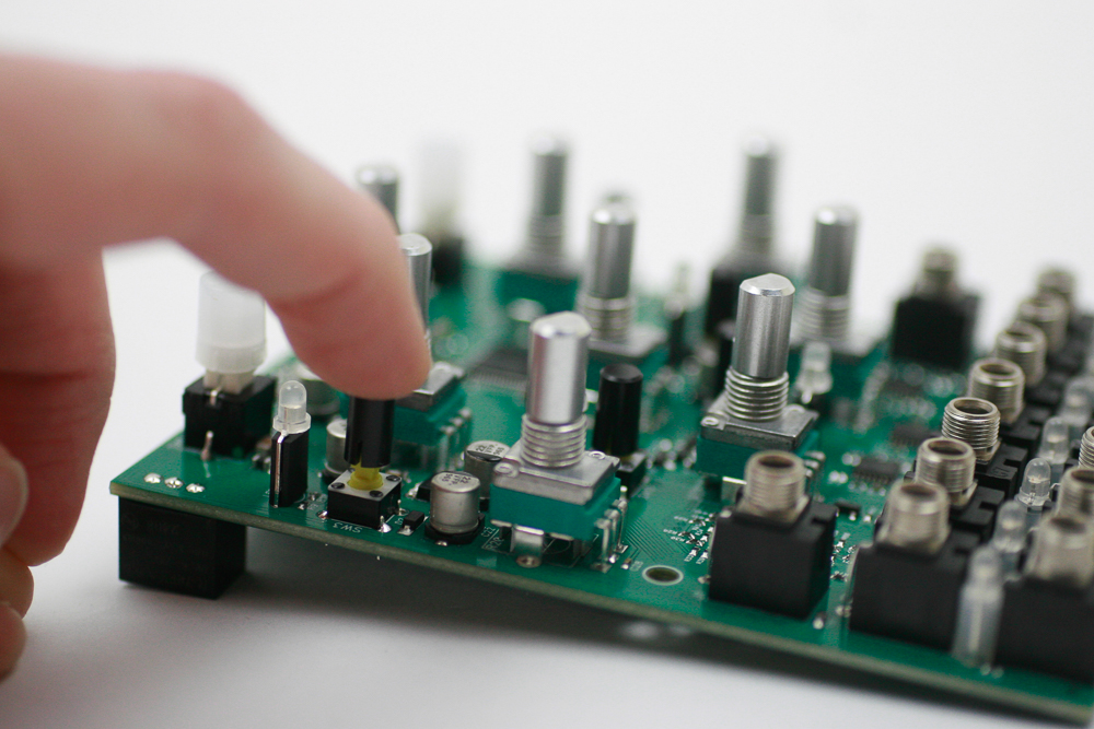
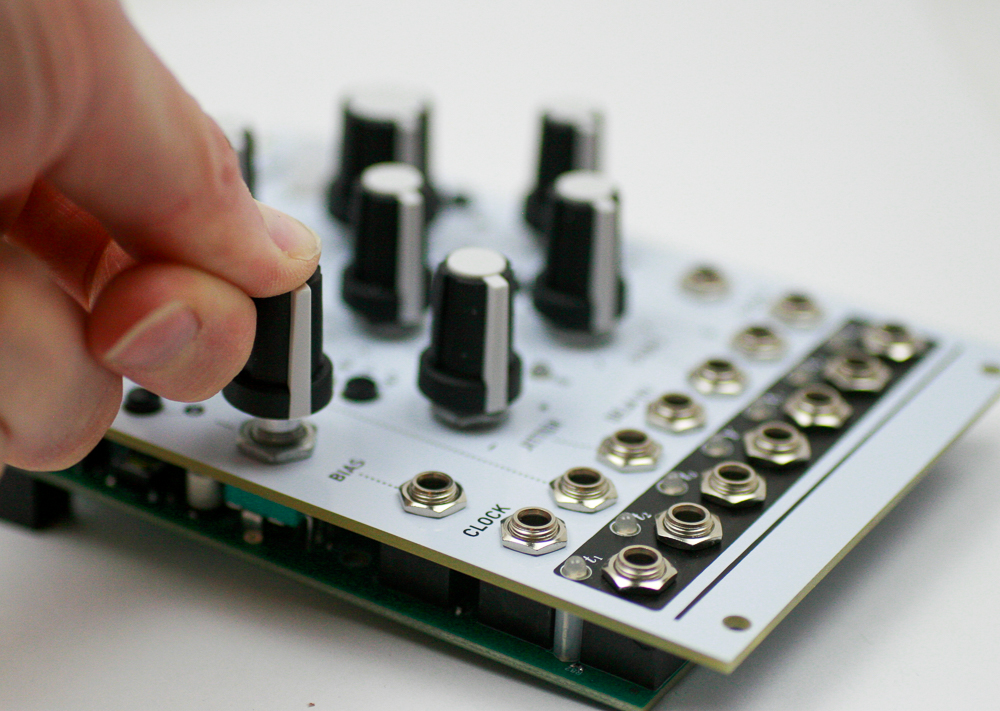
Knobs
Place the knobs into the PCB as shown below.
Congrats! We’ve already programmed the firmware, and no calibration is needed. Make sure the basic functions are working, and then test your module.