Important Links
Product Page
Assembly Instructions
Bill of Materials
Calibration Guide
Github
Midi 2 CV Assembly Instructions
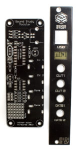
Thank you for purchasing the Sound Study Modular Midi 2 CV kit!
ATTN: Please follow the BOM and these instructions. Don’t populate from the PCB silkscreen or these instruction pictures alone. Our components may look different from the pictures, so please look over your parts and check the codes first.
The Sound Study Modular MIDI 2 CV is a clone of the Mutable Instruments CV PAL. The CV Pal is an open source project licensed under the CC-BY-SA 3.0 license. If you are seeking support, have ANY questions, or need ANY assistance whatsoever with Sound Study Modular PCB’s, kits, or assembled modules, then DO NOT contact Mutable Instruments for any reason related to this product. Sound Study Modular will assist with service, support and any other questions that you may have. You can contact us at soundstudymodular@gmail.com
If you are building the console version instead of the Eurorack version, follow the assembly instructions normally up until the electrolytic capacitor, and then follow this link to the console version instructions.
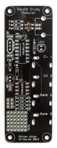
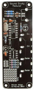
Diodes
Up first are the two diodes, These are polarized components, so make sure to line up the stripe on the diode with the stripe on the silkscreen. When you have them populated, flip your project over on a flat surface and solder them in place, clipping the excess leads.
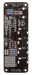
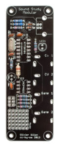
Resistors
Up next are the resistors. These are non polarized, so it doesn’t matter which direction they go, but it makes troubleshooting much easier if they are all oriented the same direction. Once you have them all in their correct places, you can flip your project over and solder, clipping the excess leads.
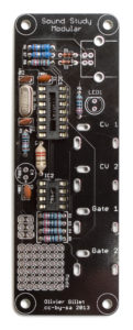
Crystal
Next is the 20Mhz crystal. This is what keeps time for the crystal. It is non polarized, so populate it in either direction. Then flip your project over and solder it in place. Clip excess leads as necessary.
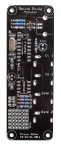
Ceramic Capacitors
Now we can populate the ceramic capacitors. These are non polarized as well, so they can be populated in either direction, but it is recommended to place them so that the numbers written on them can be easily read. This will help if you need to troubleshoot your build later.
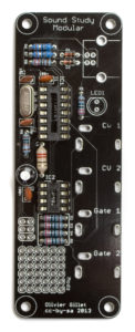
22uH Inductor
Next up is the 22uH inductor. This guy looks like a large resistor, and is also non polarized. Populate it in its correct spot as per the BOM, and then flip your project over and solder it into place, clipping any excess leads.
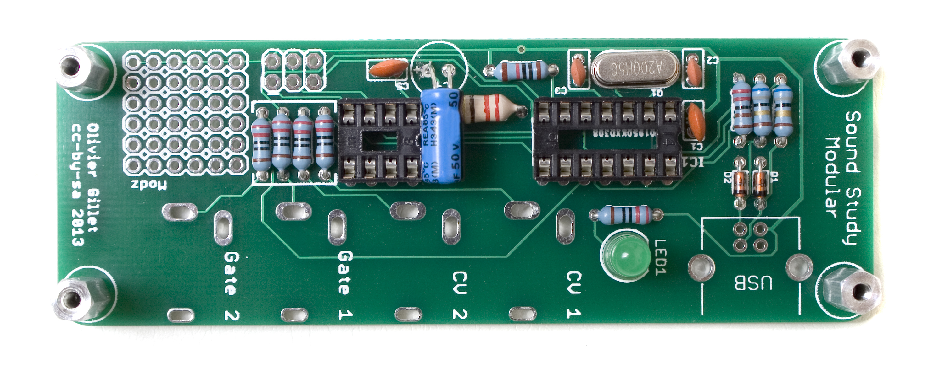
IC Sockets
Now we can populate the IC sockets. Make sure when you are populating these that you line up the notch in one side of the socket with the matching socket on the PCB. A trick to getting these guys flat is to only solder one or two legs on opposing corners, and then reheat the solder joints while applying gentle pressure on the top so that it sits flat when the solder reheats. Then you can finish soldering the remaining pins.
Click Here for the Console Version
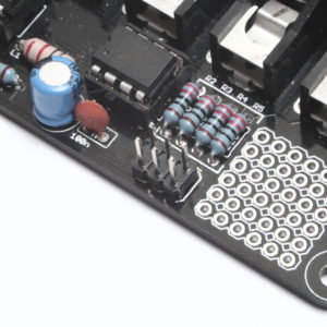
Electrolytic Capacitors
The electrolytic capacitors are polarized, so they must be oriented in a specific manner. When populating them, align the longer leg of the capacitor with the + symbol on the silkscreen. Once you have it correctly populated, flip your project over and solder everything in place, clipping any excess leads.
ISP Header
The ISP header is optional and not required for the module to function. You only need it if you plan on reprogramming the module, or if you sourced your own parts. If you bought a kit from us, you do not need to install this header.
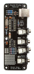
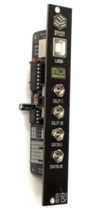
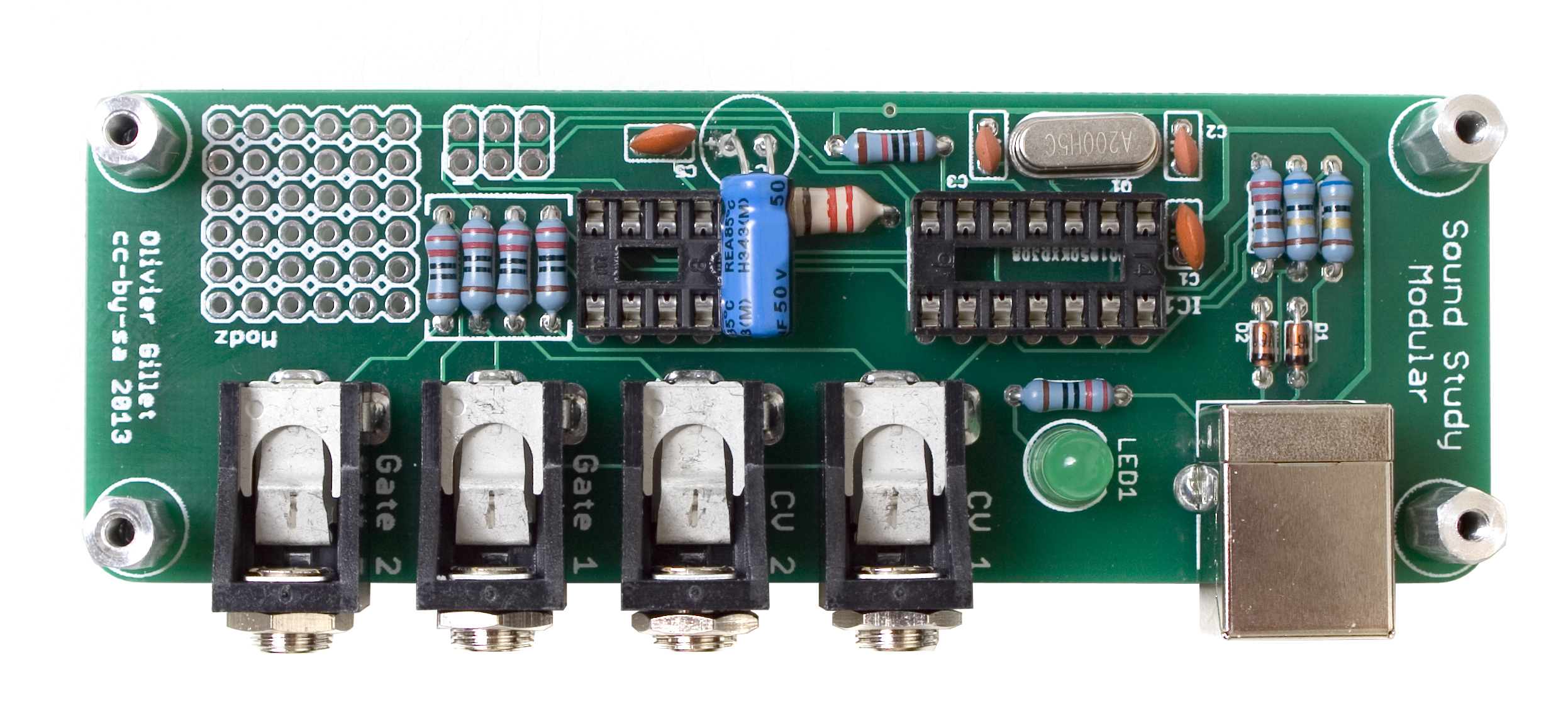
Front Panel Fitment
Now that all of the board components are in, its time to fit the front panel to the main board.
DO NOT SOLDER ANYTHING YET.
Start by placing all the components into their spots.
Now place the front panel over the jacks, making sure everything sits flat. The front panel should be at a right angle to the main board.
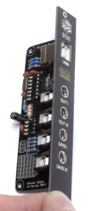
Next, use a tool to tighten the 3.5mm hex nuts to the jacks, securing the front panel in place.
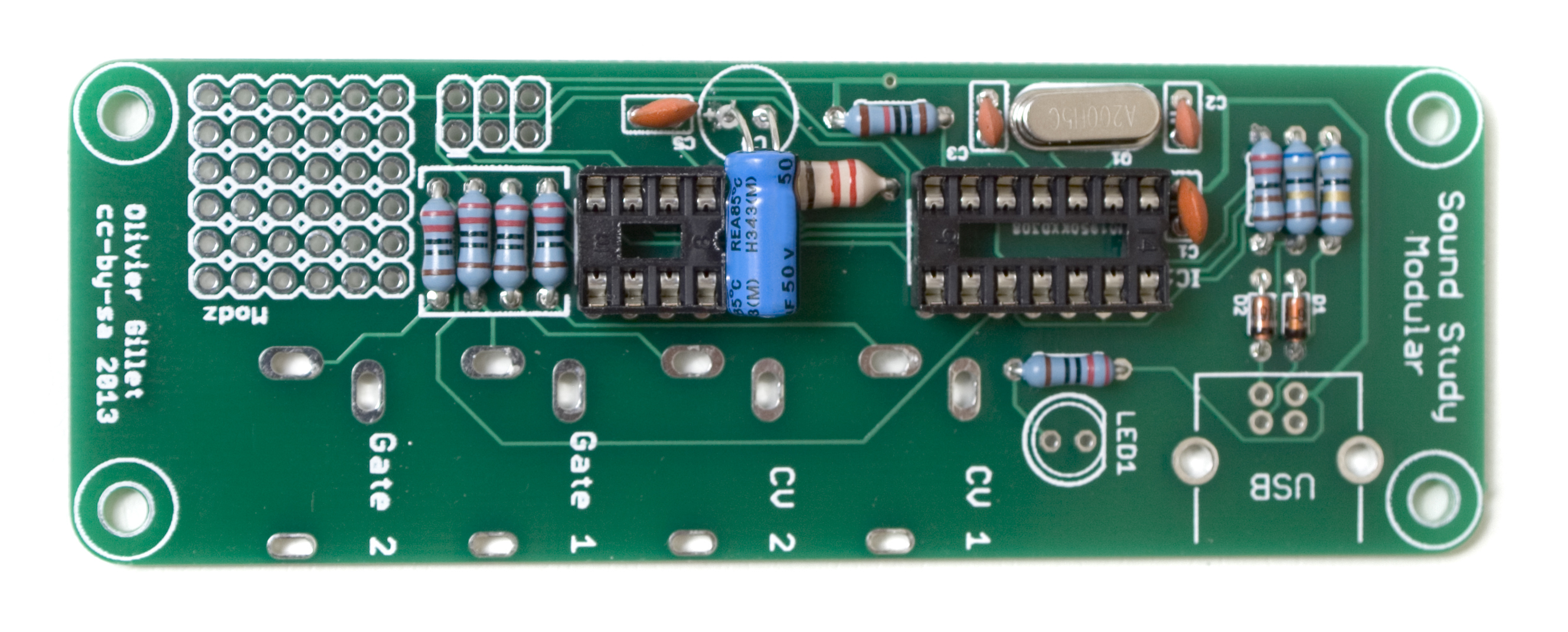
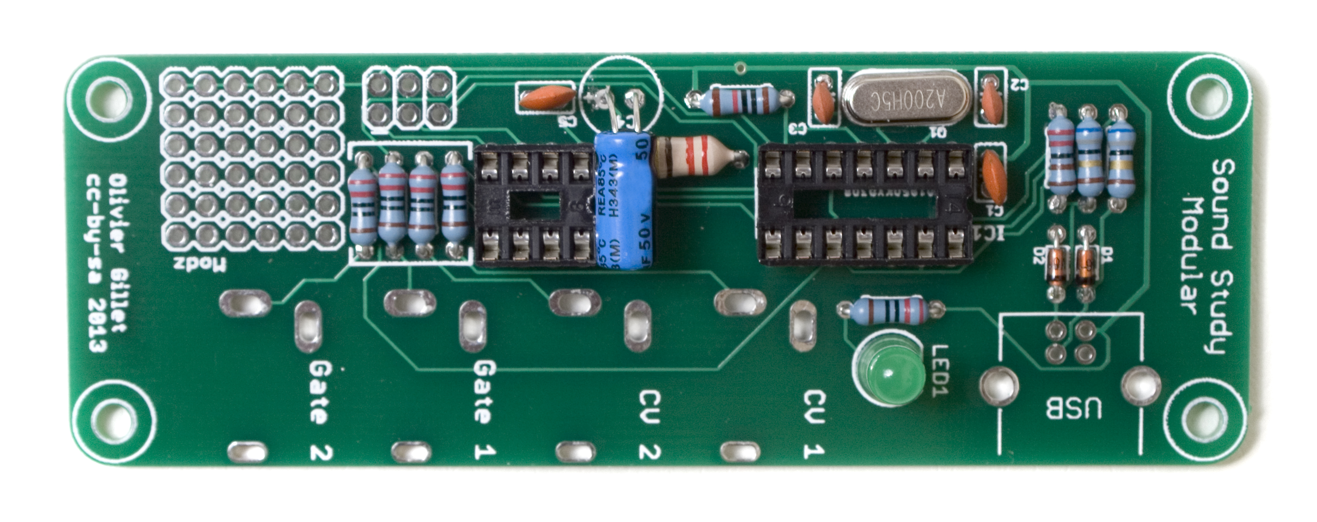
LED
Next up is the LED. This part is polarized, so care must be taken to orient it properly. The longer leg of the LED should go OPPOSITE the flat side that is indicated on the PCB.
Before populating, bend the leads for the LED at a right angle to the base of the LED. Then insert the leads through the PCB, and solder ONE leg of the LED.
Next, gently grip the LED and move it so that it is pointing at the middle of the MIDI logo. Now solder the remaining lead, and clip the excess.
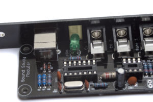
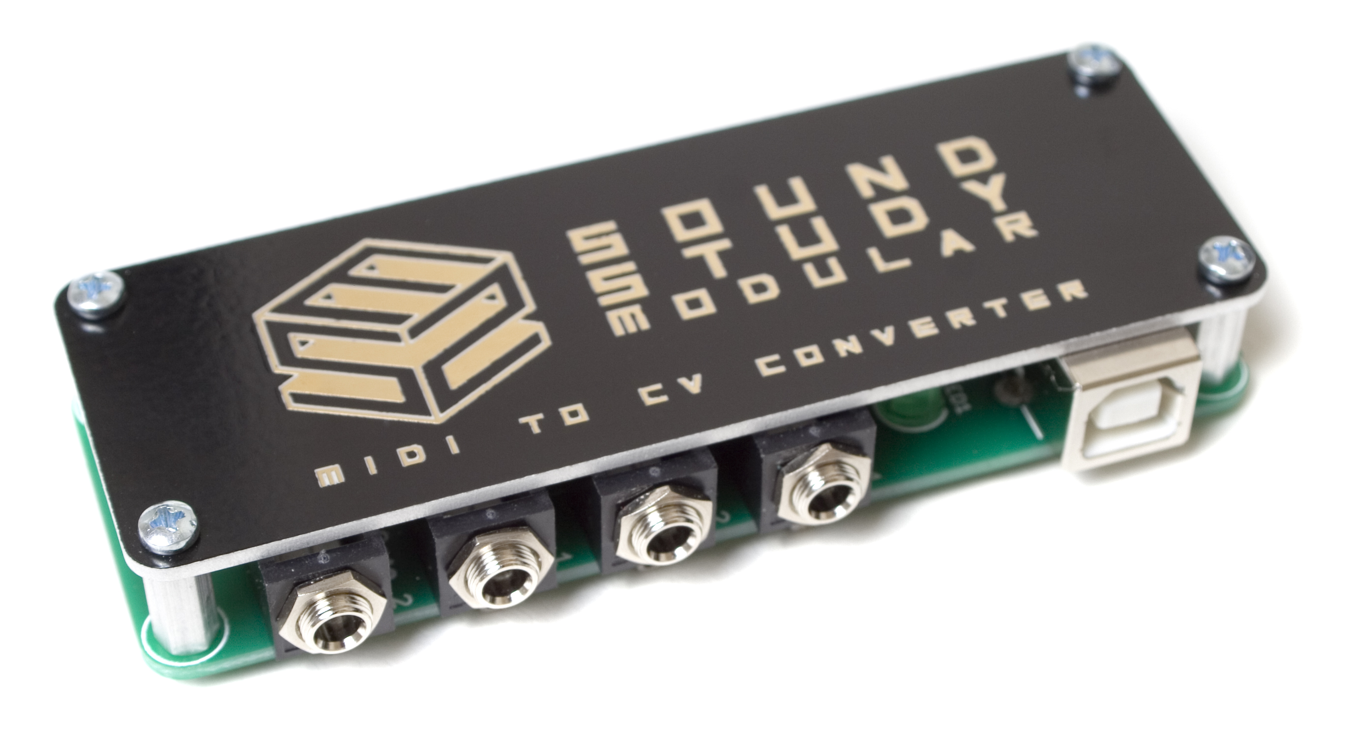
Completed Module
Congratulations on completing the Sound Study Modular Midi 2 CV module! Please continue on to the programming instructions below (scroll down below the console version instructions).
Console Version Instructions
The instructions below are for building the console version of the Midi 2 CV instead of the Eurorack Version. Follow the above instructions until the electrolytic capacitor, then continue below.
Electrolytic Capacitor
Start with the electrolytic capacitor. The electrolytic capacitor are polarized, so they must be oriented in a specific manner. When populating it, align the longer leg of the capacitor with the + symbol on the silkscreen. Bend it over so that it fits right next to the IC socket, as shown above. When you have it sitting right, flip your project over and solder it in place, clipping the leads. To help get it nice and flat, you can solder just one leg of the capacitor, then re align it by reheating a leg of the capacitor and seating the capacitor down.
LED
Next up is the LED. LEDs are polarized, so make sure when you are populating it, that you match the flat side of the LED with the flat side of the indicator on the PCB. Seat it all the way against the board, and solder it in place, clipping the excess leads.
11mm Standoffs
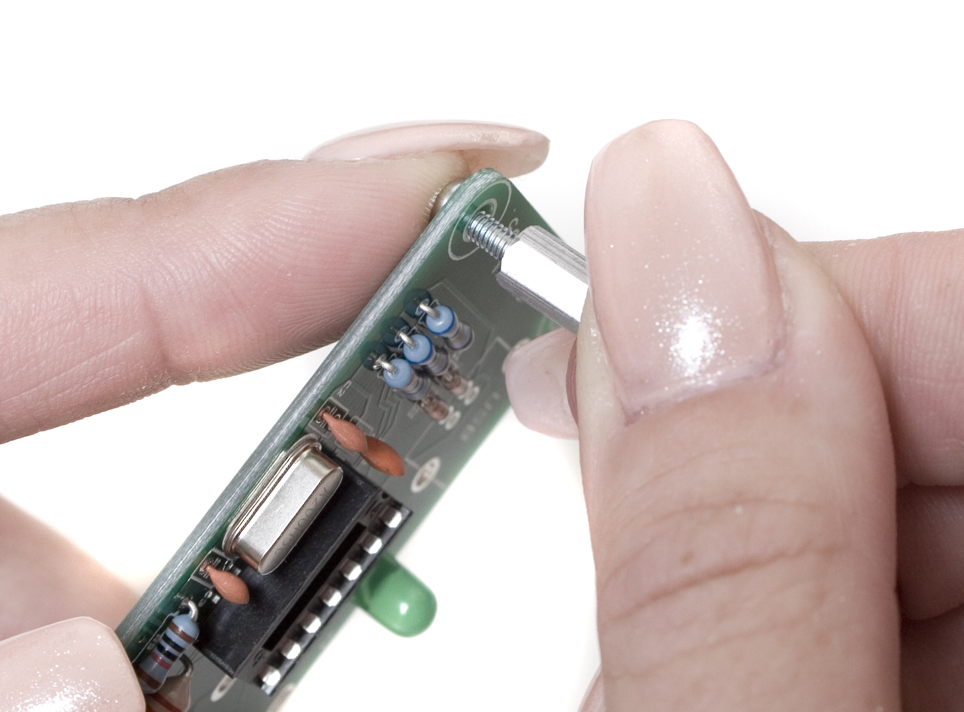
Now you can install the four standoffs on the PCB. Start by holding the 2.5mm screw through the board with one finger, and screwing the standoff down onto it from the other side. Do this with all four corners, so your project looks like the picture below.
Jacks
 Next up are the audio and USB jacks. Fit them into the PCB as shown above, and then make sure they are all sitting flat and straight. Once they look good, carefully flip your project over and solder them in place. It is important to go slow on this step, as there isn’t a front panel to hold them straight for you while soldering.
ICs
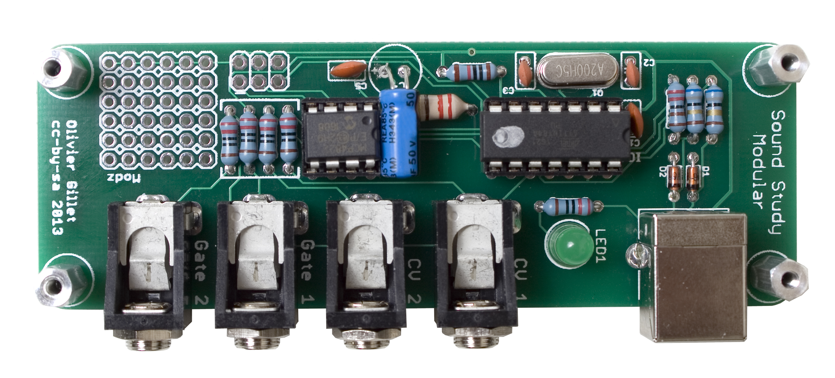
Insert the ICs into their sockets, making sure to align the half moon notch with the same looking notch in the socket. Firmly press them in to make sure they won’t wiggle loose during normal operation.
Cover
Sit the cover over the four standoffs, so that the holes line up with the tops of the standoffs. Then take a phillips head screwdriver and screw the remaining four 2.5mm screws into each one.
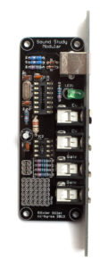
Completed Unit
Congratulations! You’ve just completed building the Midi 2 CV console version! Please keep reading to learn how to properly calibrate your new module!
Programming Instructions
QC Check Instructions
Follow the steps below to check your module and make sure its working properly.
To test your Midi 2 CV, you will need a computer with a DAW, and some other eurorack modules to test the gate and cv outputs, or you can use a multimeter to measure the voltages.
Start by plugging your Midi 2 CV into your computer, and opening your DAW.
Next, set your DAW so it outputs to the Midi 2 CV. (It’ll show up as CVPAL).
Set a sequence of notes to play, it can be anything, just a bunch of different notes.
Now take some patch cables and check that each gate output is lining up with the notes in your daw, and that the cv outputs are similarly matched up with your daw.
Midi 2 CV Calibration Instructions
Required Tools
- Digital Multimeter with at least three significant digits.
- USB Keyboard
- Computer with a DAW, or a midi through.
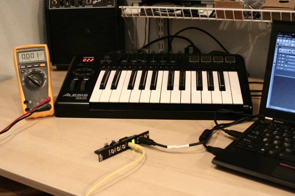
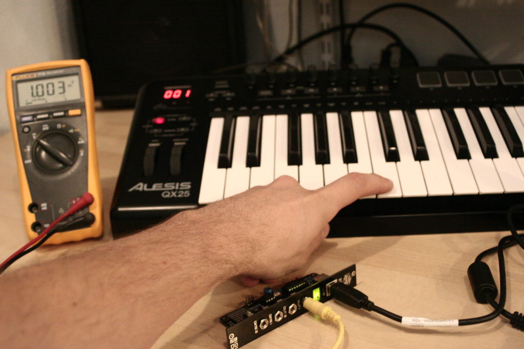
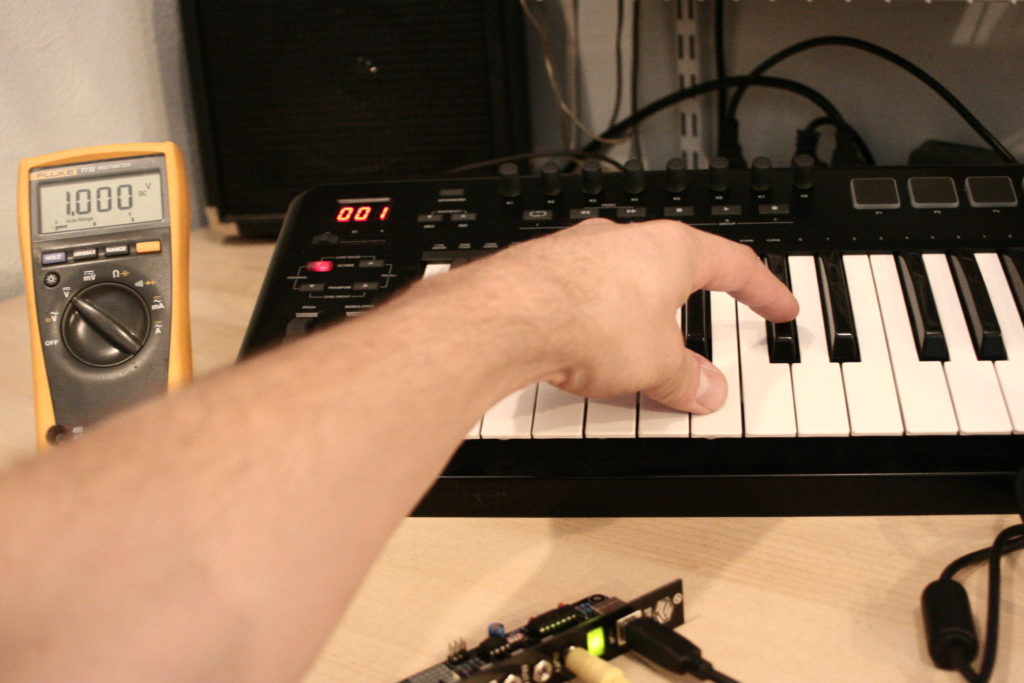
These tuning instructions will be given using an Alesis QX25 keyboard, a laptop with Linux Music Maker Studio (LMMS), and a Fluke multimeter. Any keyboard/daw setup will work, though. Just make sure that you can run the midi from the keyboard through the computer so that the Midi 2 CV Module can see the data the keyboard is sending.
NOTE: You will need the extra 100k resistor during this step
Setup
In order to have things be as accurate as possible, we will be soldering a 100k resistor to the output that you are currently testing. This resistor will be removed after calibration, and is only used to simulate a load on the jack. If you calibrate the Midi 2 CV without this resistor, you may see up to a 10c variance on tuning when patched into a 1V/O oscillator.
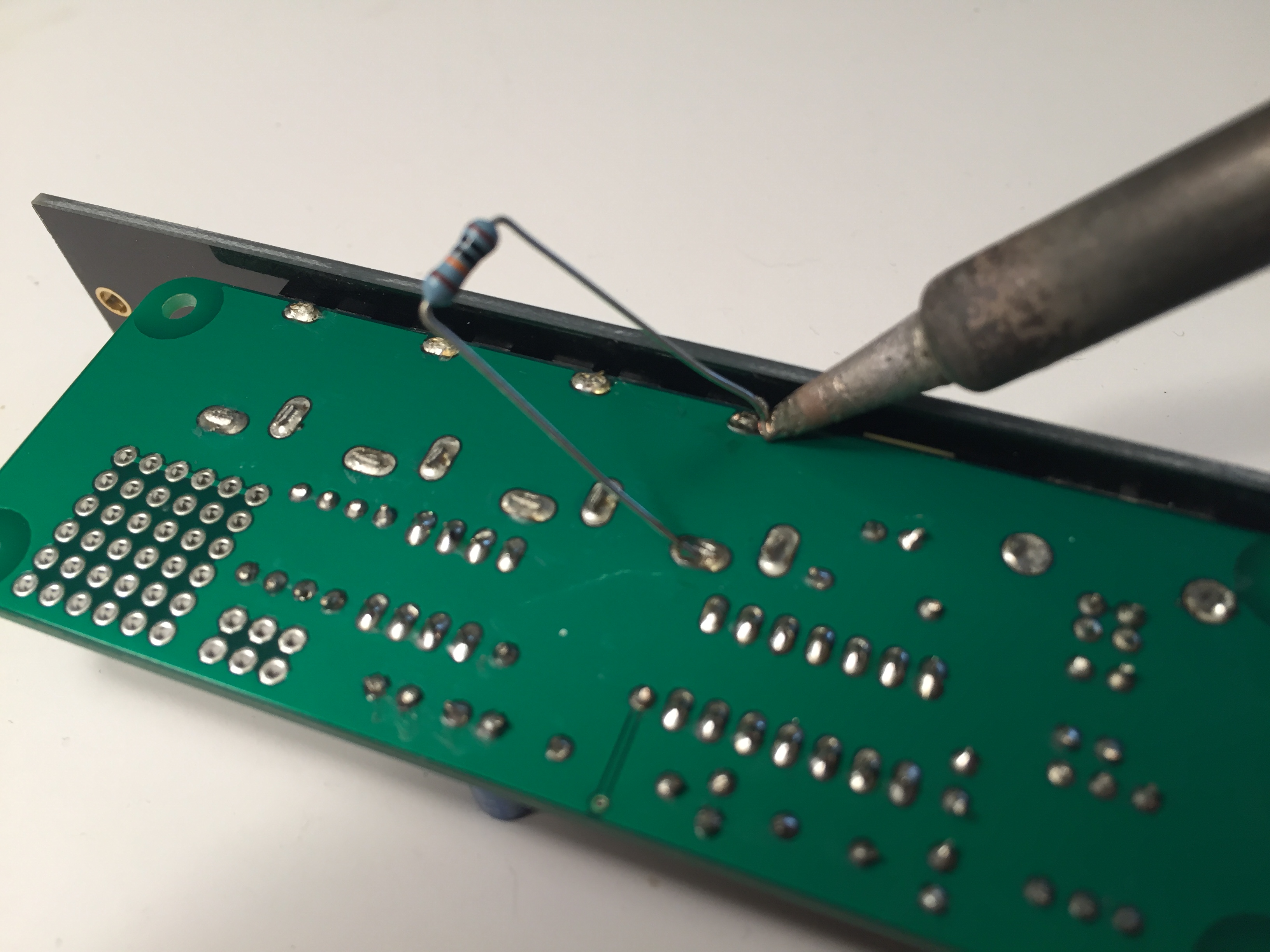
For channel 1 calibration, solder the 100k resistor as shown above.
When calibrating channel 1 (OUT1), solder the 100k resistor to the ground pin and the Tip pin of the OUT1 jack, as shown above.
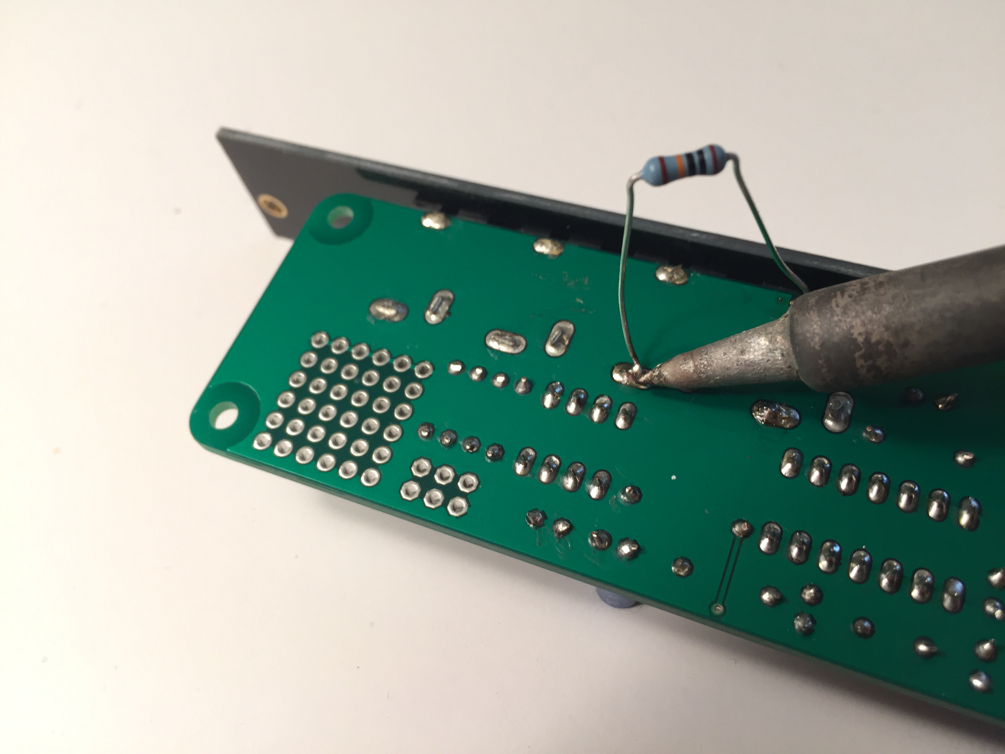
For channel 2 calibration, solder the 100k resistor as shown above.
When calibrating channel 2, desolder the resistor from the Tip of OUT1, and solder the same leg to the Tip of OUT2, as shown above.
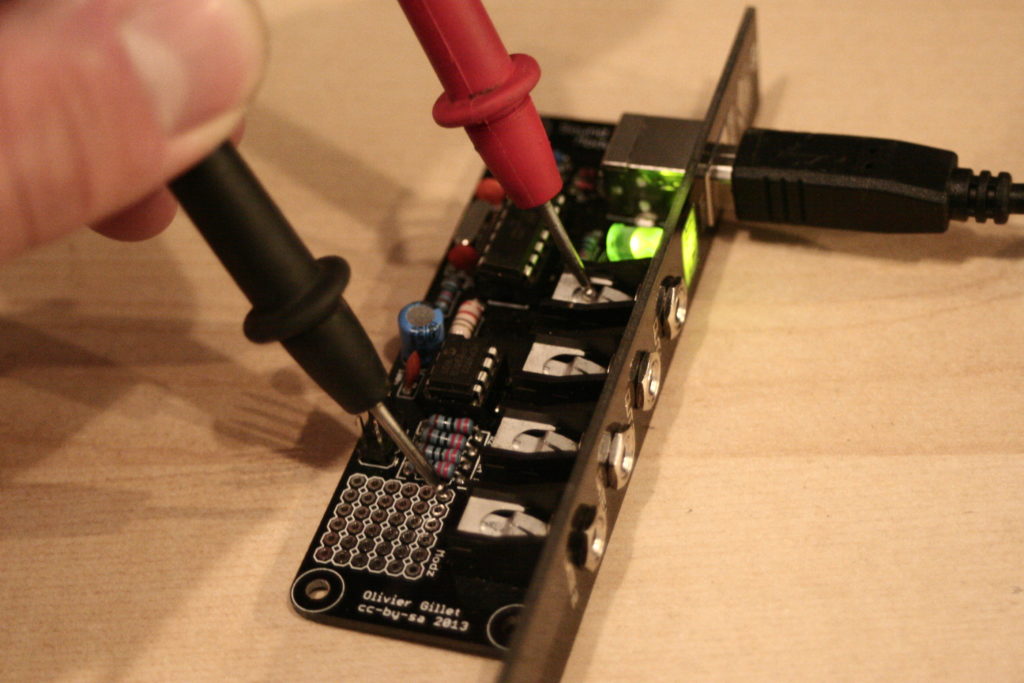
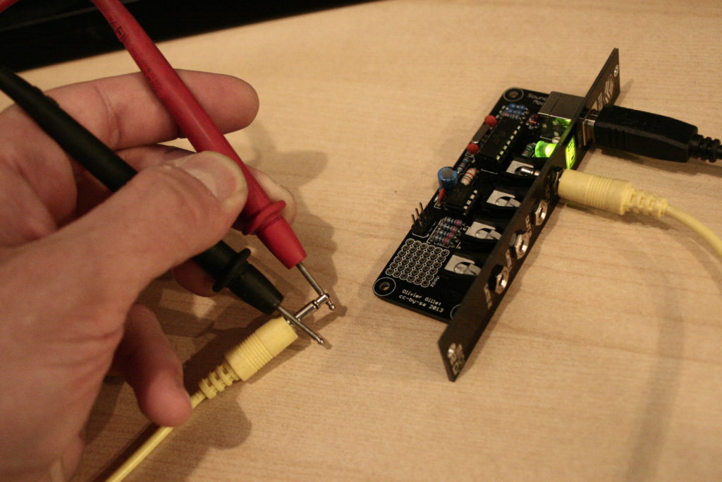
To get everything set up, plug both the keyboard and the Midi 2 CV module into your computer. Plug a patch cable into ‘OUT1’ and, using test leads, attach them to your multimeter. The red probe goes to the tip, and the black probe goes to the sleeve. If you don’t have test leads, you can just hold the probes to either the jack, or the tip of the wire, as shown below:
Set your keyboard to transmit on channel 15. On the QX25, first make sure all three zones are using the global channel, and then set the global channel to 15. This will let us adjust ‘OUT1’. We will have to come back and repeat the whole process on channel 16 to set ‘OUT2’.
Channels 15 and 16 are ONLY used for calibration of CVout1 and CVout2. (remember to change over the load resistor!)
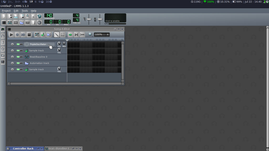
In LMMS, start a new project, and then click on the ‘Triple Oscillator’ that should already be there by default.
Then click on the MIDI tab (about a third down the new menu) and configure the two dropdowns so they look like the pictures below. We want to set our MIDI input device as the keyboard, and the output as the Midi 2 CV (will show up as CVPAL). Make sure you select channel 15 (or 16 if your doing the second channel) on the output device.
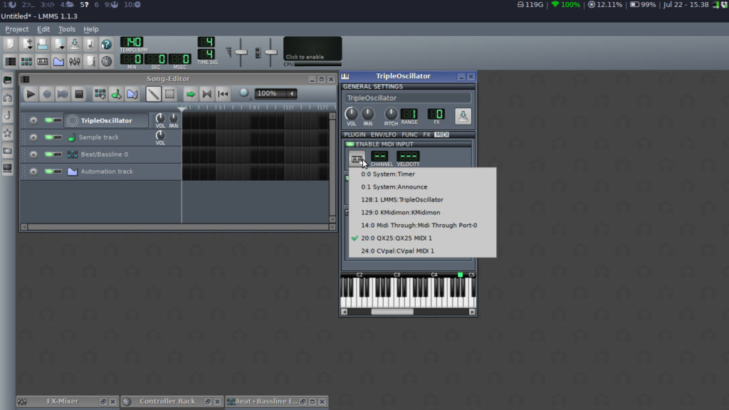
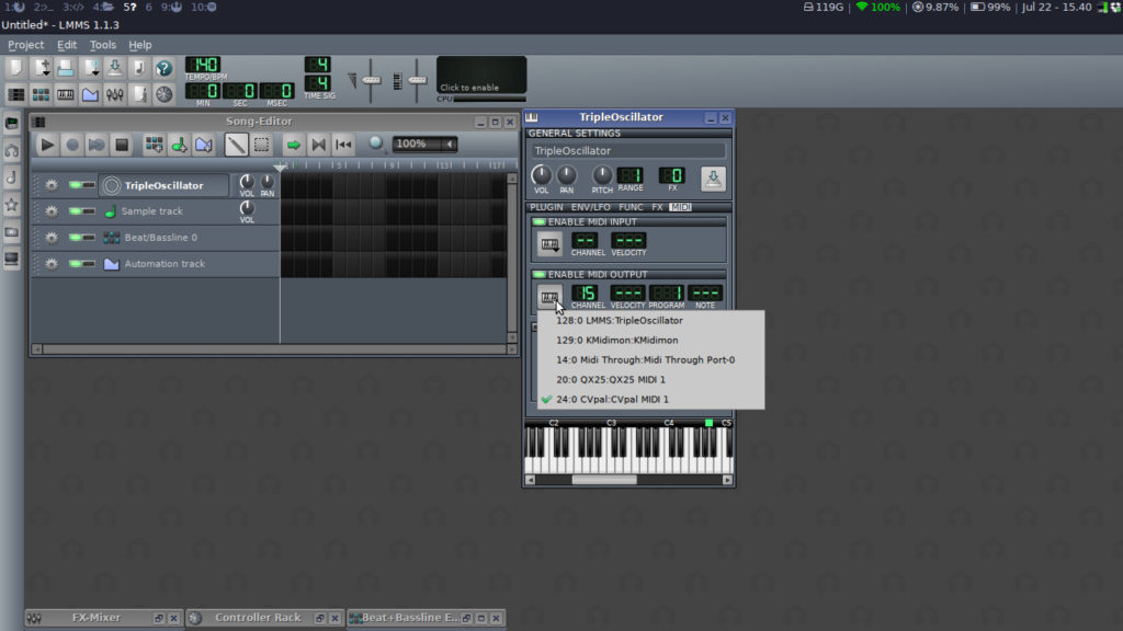
Here is a picture of the full setup:
Calibration
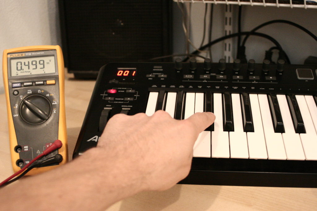
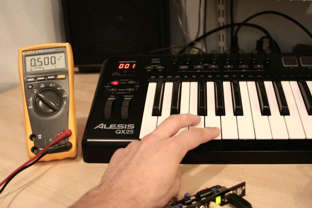
The first calibration note is F#2. This should produce 500mV out of ‘OUT1’. Use the keys immediately on either side of F#2 to move the voltage up or down by 1mV. We want this first one to be as close to 500mV as we can get.
Then Next note to calibrate is C3. Just like before, use the keys immediately left or right of C3 to tune the voltage up or down. This note should be as close to 1.000v as possible.
We are going to continue this pattern for three more octaves. Please refer to the table below for the notes to play, and what voltages you should see at each note.
| Note | Voltage |
| F#2 | 0.500 |
| C3 | 1.000 |
| F#3 | 1.500 |
| C4 | 2.000 |
| F#4 | 2.500 |
| C5 | 3.000 |
| F#5 | 3.500 |
| C6 | 4.000 |
Once you have reached C6 and it is reading 4v, go back into LMMS and set the output to channel 16, and also make sure that you set your keyboard to channel 16 as well. Also remember to switch the patch cable from ‘OUT1’ to ‘OUT2’ if you are using a patch cable.
Channel 16 is the calibration channel for ‘OUT2’. Go back to the beginning of the calibration and go through it again, but with channel 2. (remember to change over the load resistor!)
Once you have done that, you should be good to go. You can mount the Midi 2 CV in your rack and make some music!