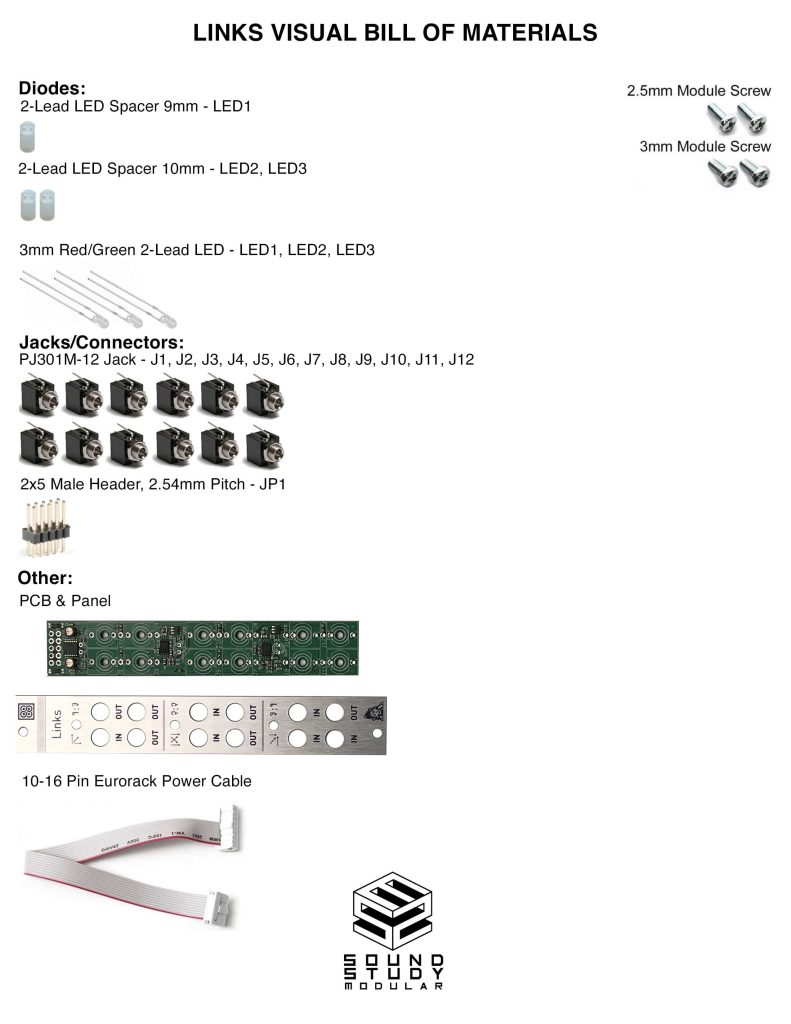
Click here for a bill of materials with Mouser part numbers.
LEDs
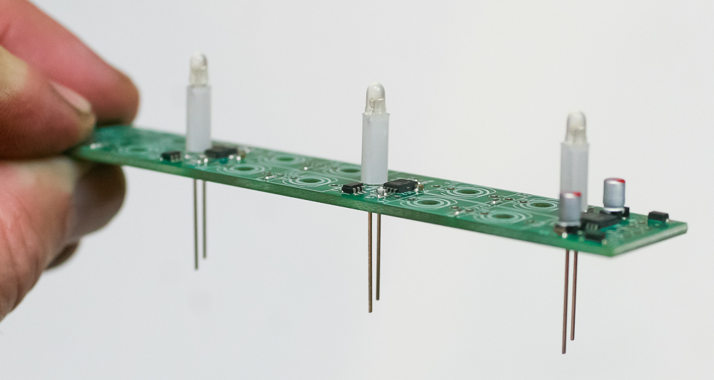
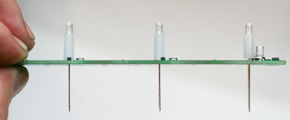
First place the LEDs into the LED spacers. The LED closest to the power header (LED1) uses a 9mm spacer; the other two use 10mm. Align the flat side of the LED with the flat side on the PCB silkscreen. Carefully turn over to solder in place. Keep them vertical, with the spacers flush to the PCB.
Jacks
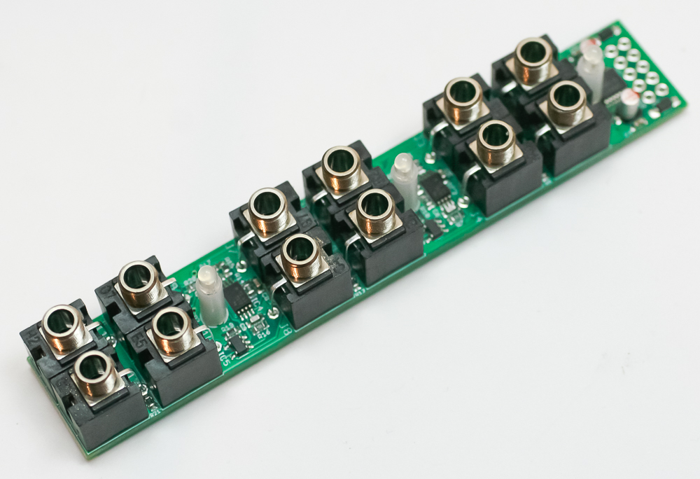
Populate all of the jacks as shown below. Carefully turn over to solder in place. You can use the panel to help if you like.
Power Header
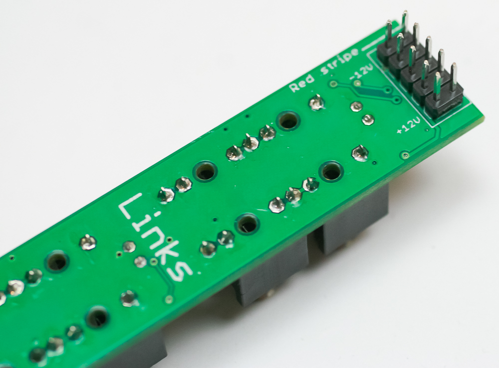
Populate the power header as shown below. Carefully turn over to solder in place.
Power Header
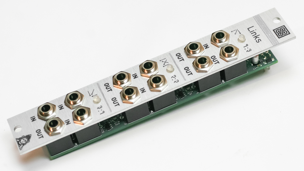
Place the panel over the project
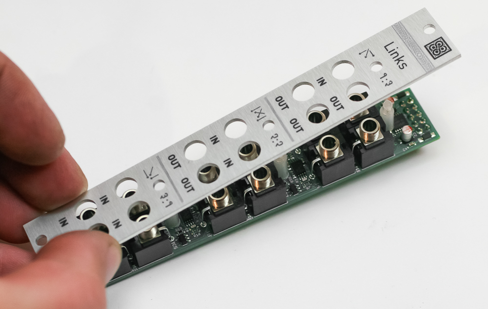
Finally, gently tighten down the jack nuts. Links doesn’t have any code, and no calibration is needed. You are now ready to test your build!