Thank you for purchasing the Erica Synths MIDI-CV SMT Kit!
Through hole kits:
We previously sold a through hole kit that was straight clone of the MIDI-CVII. An assembly guide is available at the Erica Synths Github here.
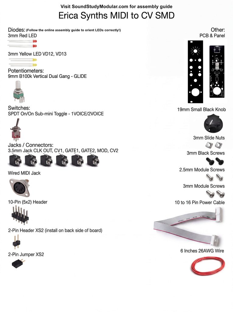
SMD PCB

2 PIN HEADER

Populate the 2 pin header and place the jumper on. Module will not function without this.
JACKS, POT & SWITCH
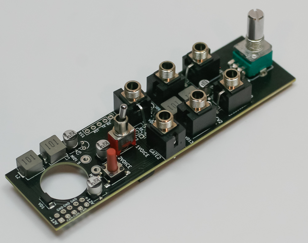
Place the jacks, pot and switch into the PCB as shown above
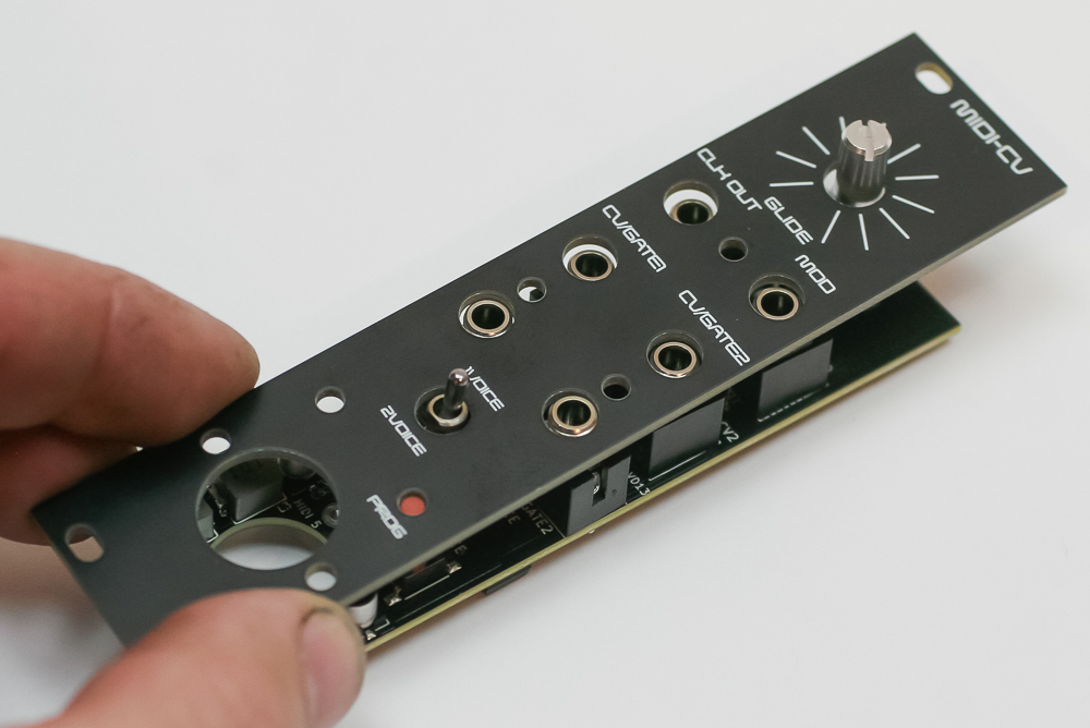
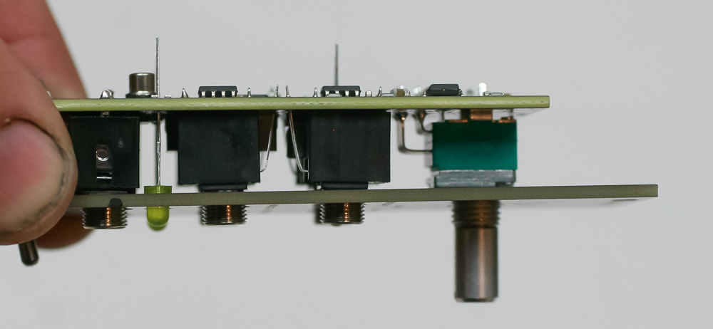
Now place the panel over the project to keep the components aligned for soldering. Carefully turn project over and solder the components (keep them straight!) in place.
LEDs
LEDs are polarized and MUST be placed into the PCB properly. The two yellow LEDs have a “+” marking on the silk screen that indicates the anode or LONGER lead of the LED. Let’s first populate the LEDs according to their proper orientation, then we can solder them in later once we place the panel over the project. The two RED LEDs need to be placed into the PCB as shown below:
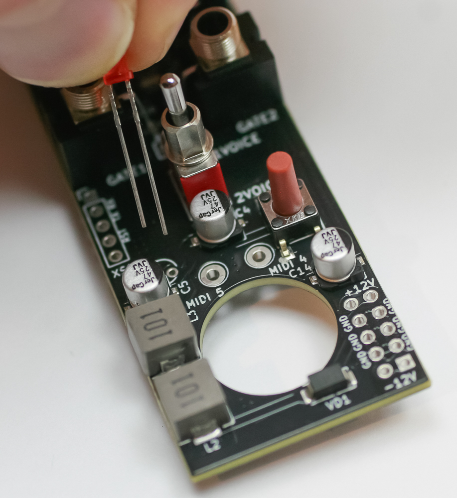
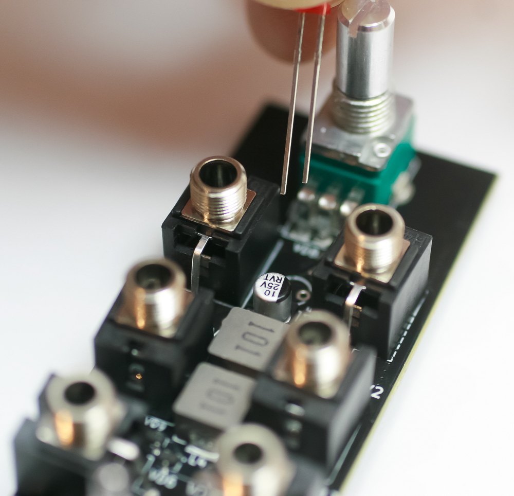
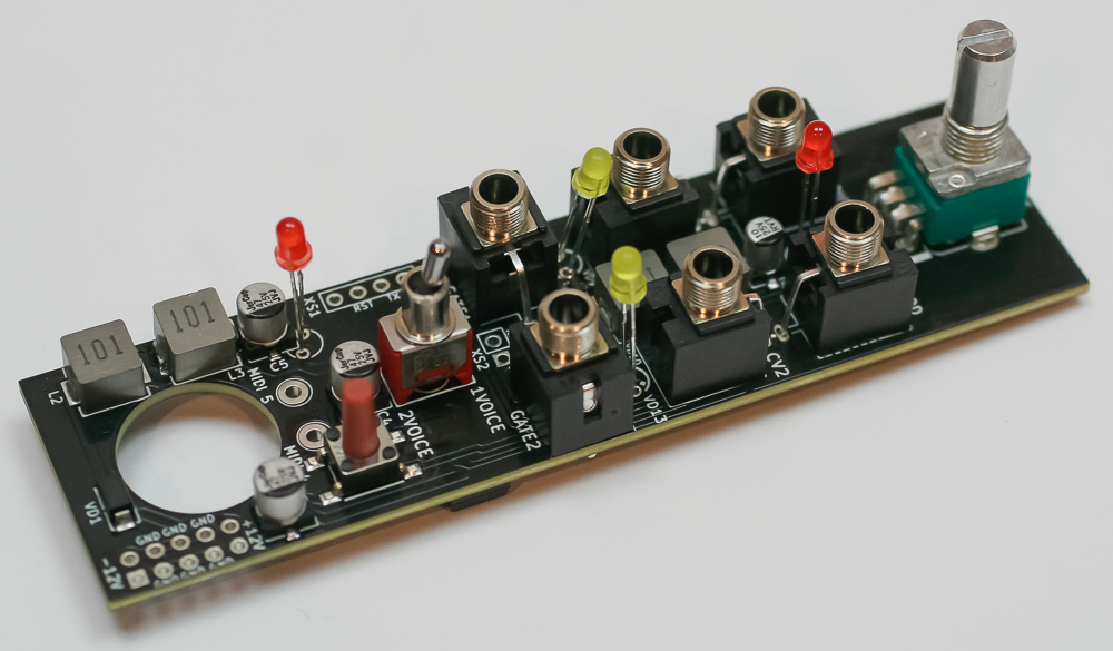
Don’t solder just yet. First, temporarily place the panel back over the project (finger tighten a couple nuts) so that you can press the LEDs through the panel to achieve the proper depth. Once you do that, you can solder the LEDs in place.
POWER CONNECTOR
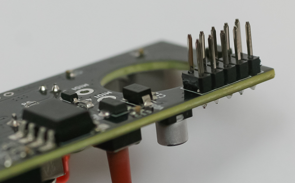
Now place the 5×2 row 10-pin power header into the PCB and carefully turn the project over to solder in place.
MIDI JACK
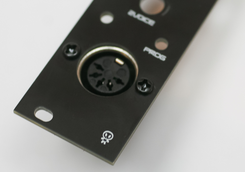
First, use the small square nuts and the 2 black 3mm screws and attach the MIDI jack to the Panel as shown below
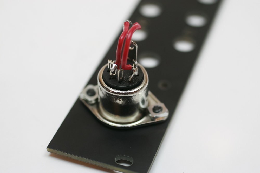
Now take some short leads of wire and attach them to the 2nd and 4th pins of the MIDI jack (moving clockwise). It can be easier to cut and strip the wire first.
now connect the wires (pin 2 -> MIDI 4, pin 4 -> MIDI 5)
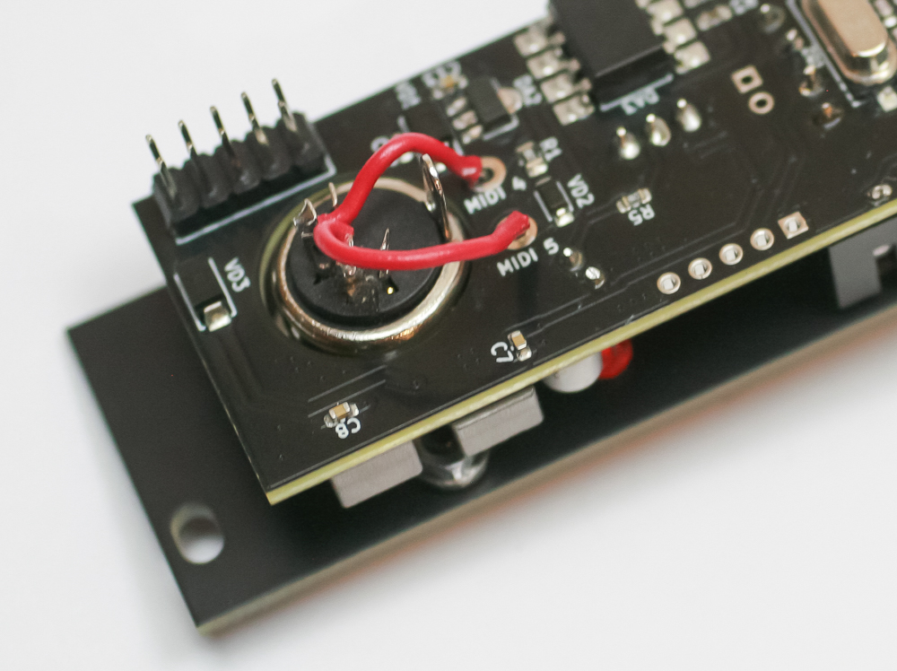
Next, fully engage the panel to the other PCB components and tighten down the nuts.
CALIBRATION
You will need a VCO with good 1V/oct tracking, midi keyboard and a chromatic tuner.
- Connect midi keyboard to the module, set VOICE switch to 1 Voice mode and connect CV1 output to a calibrated VCO (1V/oct) input and a chromatic tuner to the output of the VCO.
- Turn off the power to the module. Then push and hold PROGRAM button (PROG) while powering it back on. The MIDI LED will start to blink, which means the module is in calibration mode.
- Play C3 on the keyboard, and tune the VCO so that tuner reads C3.
- Play C4 on the keyboard and check the reading on the tuner. If it reads something higher than C4, play B3 on the keyboard repeatedly until the tuner reads C4. If it reads something lower than C4, play C# repeatedly until the tuner reads C4.
- Play C5 on the keyboard and check the tuner. If it reads something higher than C5, play repeatedly B4 until the tuner reads C5, etc.
- Continue until you have perfect tuning along all octaves.
- Push the PROGRAM button to quit calibration mode.
To learn about all the new features included in the MIDICVX firmware, check out the manual here.