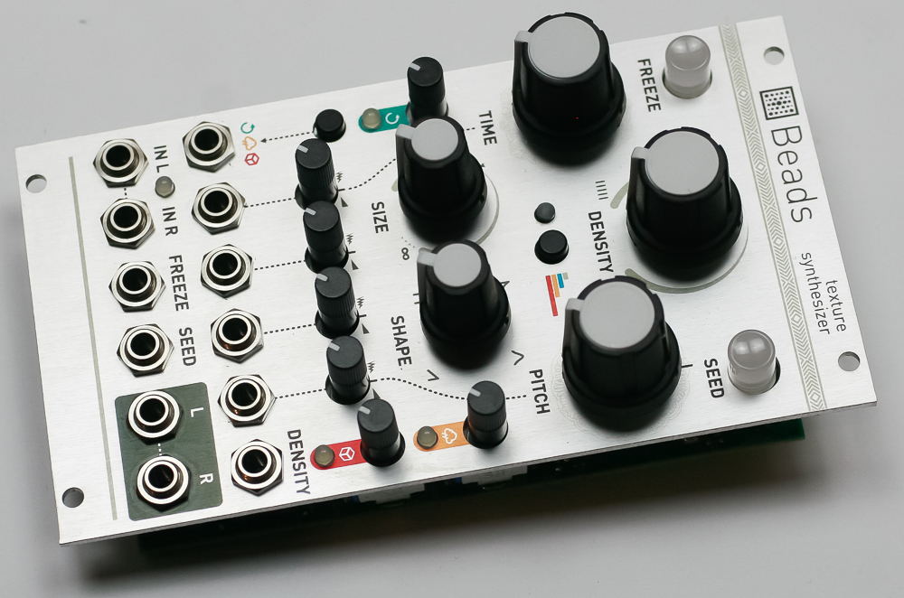
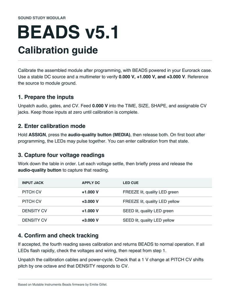
Important note: This is a guide to assembling our finish-it-yourself kit. The SMD parts are already populated, and the firmware is pre-programmed.
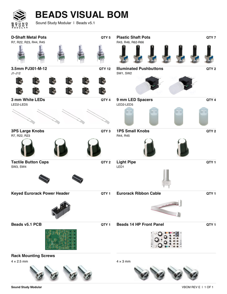
LEDs
First, slip the LED spacers on all of the LEDs.
The LONG leg of the LED is oriented to the RIGHT (where there is a small but visible “+”). There is also a flatter side of the LED silkscreen which aligns with the shorter lead.
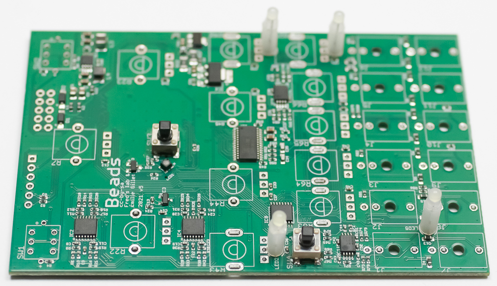
Jacks
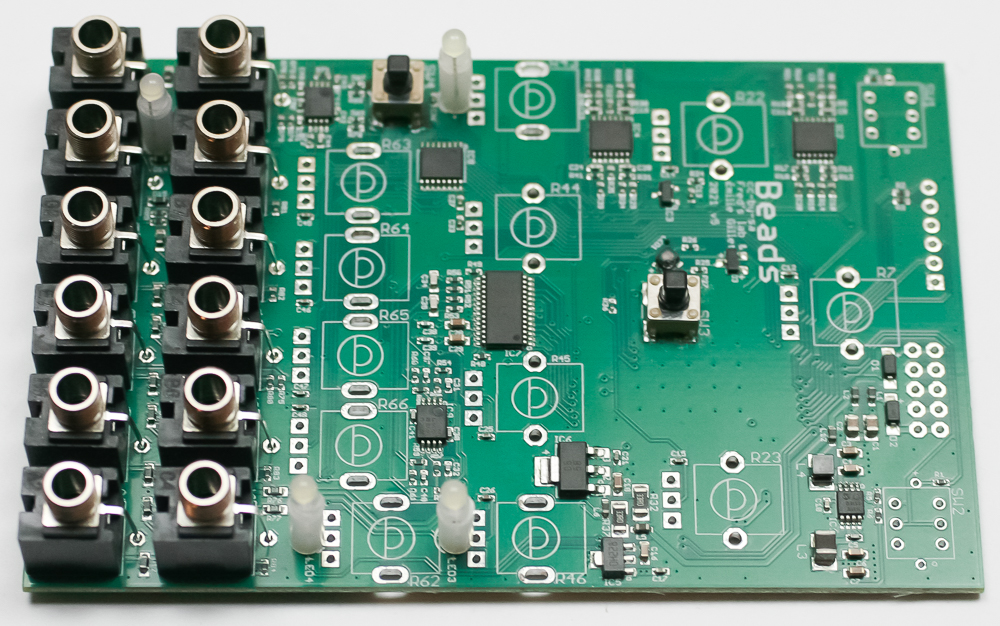
Place the jacks into the PCB as shown below. Carefully turn the project over to solder in place. You can use the panel to make sure that the jacks all stay in place.
Push Button Switches
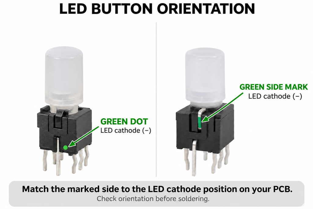
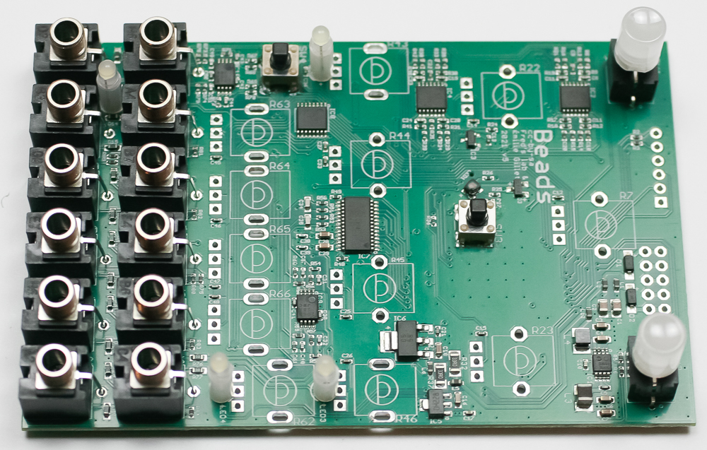
Carefully place the LED push button switches into the PCB as shown below. Make sure to align the green dot/mark on the switch with the white dot on the silkscreen.
Potentiometers
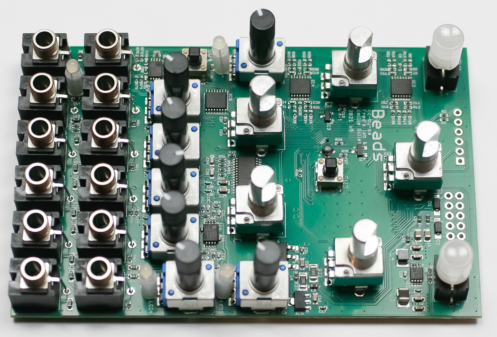
Place all of the pots into the PCB as shown below. Carefully turn the project over to solder in place. You can use the panel to make sure that the pots all stay in place.
Power Header
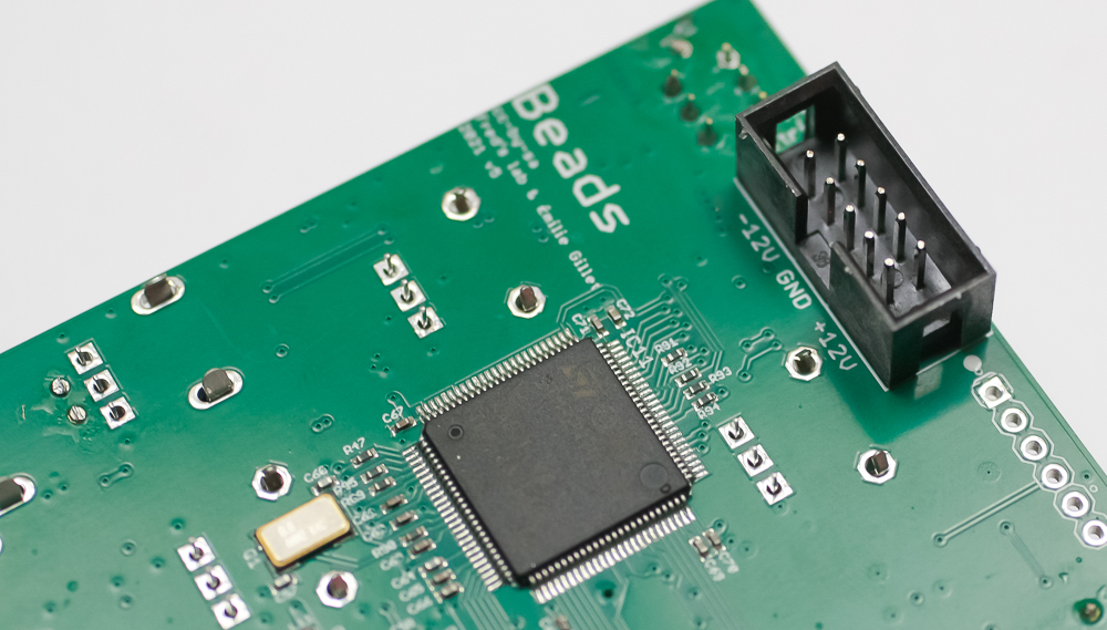
Place the 10 pin shrouded power header as shown below. Align the notch on the shroud with the notch on the PCB. Carefully turn over to solder in place.
Tact Switch Caps & Light Pipe
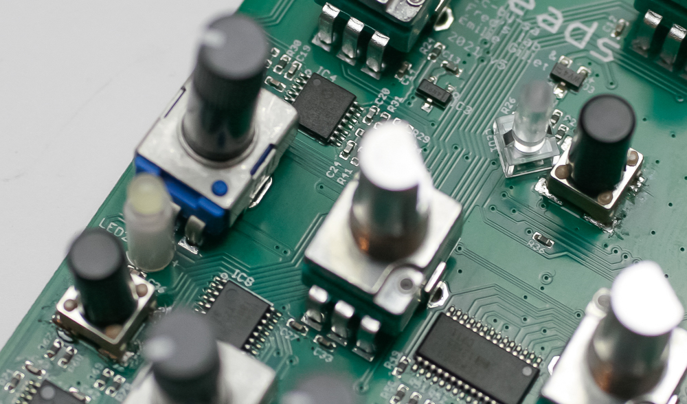
Carefully snap in the two tact switch caps and VERY CAREFULLY place the light pipe as shown below.
Panel
Carefully place the panel over your components as shown below. Take your time to make sure the LEDs don’t bend over.
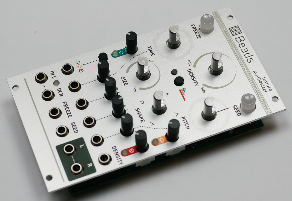
Gently tighten down the pot and jack nuts
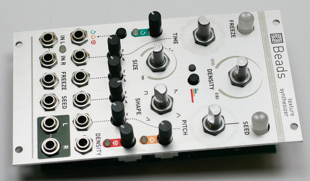
Place the Rogan knobs as shown below, you are now ready to test your module.